
Designing a double-angle connection
A double-angle connection is a simple shear connection made of two angles, one on each side of the beam web. Each side can be bolted or welded, so it covers Manual Tables 10-1 (all-bolted), 10-2 (bolted / welded) and 10-3 (all-welded).
When to use it #
- Use a double angle for a symmetric, flexible shear connection with good capacity, a beam that frames between column flanges or into a girder web, or a reaction with axial tension or compression.
- Use a single plate when the support side should be shop-welded and only one element is wanted.
- Use a single angle for light reactions where a one-sided connection is acceptable.
- Use a shear end plate when the element should be shop-welded to the beam end.
The two legs have their own names in the app. The beam legs lie against the beam web. The outstanding legs lie against the support. Welds A join the beam legs to the beam web. Welds B join the outstanding legs to the support.
Creating one in the wizard #
- In the wizard's Connection type step, select the Angle card in the Simple shear group, then Double angle under Angle type.
- Under Joint type, select Beam to column flange, Beam to column web, Beam to girder web or Beam to HSS column. On an HSS column the outstanding legs can be welded or bolted to the HSS (see Bolted to an HSS wall).
- Under Configuration, select a card. The first word is the beam legs, the second the outstanding legs:
| Card | Sets | Manual basis |
|---|---|---|
| All-bolted | Beam legs bolted, outstanding legs bolted | Table 10-1 |
| Bolted / Welds B | Beam legs bolted, outstanding legs welded to the support | Table 10-2 |
| Welds A / bolted | Beam legs welded to the beam web, outstanding legs bolted | Table 10-2 |
| All-welded | Welds A and Welds B | Table 10-3 |
On an HSS column all four cards are available. All-bolted and Welds A / bolted bolt the outstanding legs to the HSS wall with through-bolts by default.
- Members. Enter the Connection mark (new marks are numbered DA-1, DA-2 and so on), the Supported beam, the Column, Girder or HSS column, and Angles (each), the angle shape used for both angles.
- Loads. Choose Service D + L (Dead RD, Live RL) or Required strength (Shear Ru or Ra, and Axial with + for tension). The other load modes are in the editor.
- Tick Auto-design the connection (bolts, angles, welds) for these loads to size the connection as it is created. The wizard keeps the beam, the support, the joint type and the configuration, and uses the Lightest (steel weight) objective.
- Select Create.
Inputs in the editor #
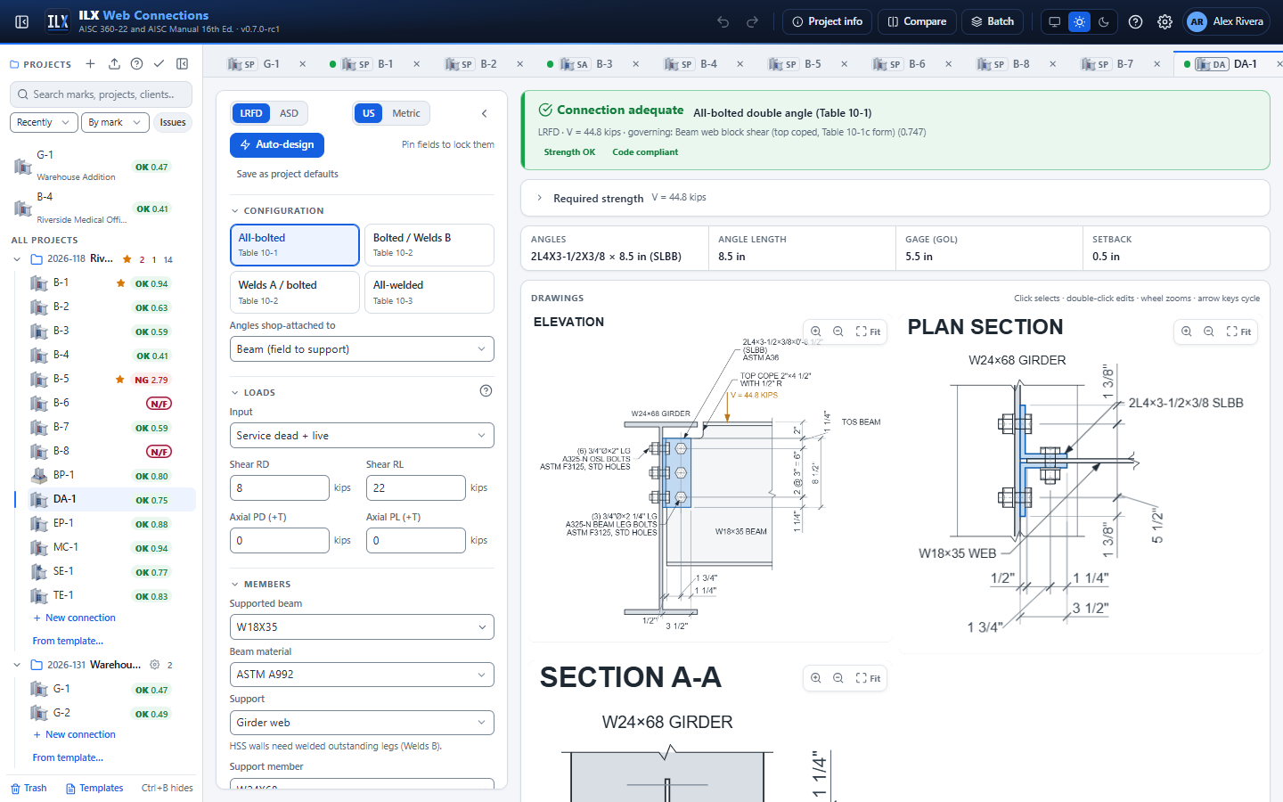
The input panel has these sections, in this order. Sections that do not apply to the configuration are hidden: Bolts for the all-welded configuration, and Welds for the all-bolted one. The key-geometry strip under the status shows Angles (for example 2L4X3-1/2X3/8 × 8-1/2 in (SLBB)), Angle length, Gage (GOL) or Beam leg, and Setback.
Configuration #
| Field | Options and notes |
|---|---|
| Configuration buttons | All-bolted (Table 10-1), Bolted / Welds B (Table 10-2), Welds A / bolted (Table 10-2), All-welded (Table 10-3). On an HSS wall the bolted-support buttons bolt the outstanding legs to the HSS; see Bolted to an HSS wall. Choosing welded outstanding legs resets Connection on the other side of the web to None. |
| Angles shop-attached to | Beam (field to support) (default) or Support (beam knifed in). With Support, ILX checks that the bottom flange can pass the beam legs during erection, and proposes a bottom cope if it cannot. The choice also sets which welds the drawing marks as field welds. |
Loads and axial force #
The Loads section is the shared one; see Loads and load combinations. All four input modes are supported: Service dead + live, Service components → ASCE 7 combinations, Required strength (Ru, Pu) and Factored load cases (table). Axial tension and compression are both supported. The demand on the beam-leg bolts and on Welds A is the resultant of the shear and the axial force.
Members and support #
| Field | Options and notes |
|---|---|
| Supported beam, Beam material | A W, M, S or HP shape |
| Support | Column flange, Column web, Girder web, and HSS column wall (rectangular). On an HSS wall the outstanding legs are welded (Welds B) or bolted with through-bolts or blind bolts. |
| Support member, Support material | A W, M, S or HP shape, or a rectangular HSS for an HSS wall. For an HSS wall, the materials are limited to A500 and A1085. Round HSS is rejected because it has no flat face. |
| Connected HSS face | HSS wall only: B (wide face) or H (narrow face) |
| Bolts into the HSS | HSS wall with bolted outstanding legs only: Through-bolts (snug-tight, J3.11b) (default) or Blind bolts (manufacturer, J3.12). See Bolted to an HSS wall. |
| Blind bolt available strength per fastener (manufacturer) | Blind bolts only. Default 0, which fails until you enter the manufacturer's value. |
| Girder TOS − beam TOS (+ = beam lower) | Girder web only. ILX checks the beam flanges against the girder flanges and fillets, and the angles against the girder fillets. |
| Connection on the other side of the web | Column web or girder web with bolted outstanding legs: None, Bolts shared (II.A-8) or Bolts staggered |
| Opposite reaction Ru (or Ra), Opposite rows sharing bolts (0 = n) | Shared bolts only: the reaction of the opposite connection, and how many of its rows share these bolts (0 means n) |
| Vertical stagger of the opposite bolts | Staggered bolts only. The opposite connection's holes also pass through these outstanding legs and reduce their net section. |
| Required stagger for wrench clearance (0 = ILX approx.) | Staggered bolts only. Your value for the offset the wrench needs to clear the neighbouring head or nut. The Manual gives none for bolts on both sides of a web (its Table 7-15 / 7-16 staggered tables cover a bolt in each leg of an angle). 0 (default) uses the ILX approximation C1 + heavy-hex head across corners/2 + 1/16 in. The report states which was used. |
| Connection near the column end, Column end to the connection force | Column web or column flange. Cleared (default): the connection is not near the column end. Ticked: enter the distance from the column end to the force. Column web: when it is less than √(8wab/(a + b)), ILX halves the Eq. 9-45 yield-line strength (Manual p. 9-18). Column flange with an axial force: web local yielding uses Eq. J10-3 when the distance is ≤ d, and web crippling Eqs. J10-5a/b when it is < d/2 (AISC 360-22 J10.2, J10.3). The report shows the limit, the distance and which equation was used. |
When you change Support, the editor does not change the support member for you. Pick a matching Support member (an HSS for an HSS wall, a W shape otherwise). Until you do, the field shows an error.
Angles #
| Field | Options and notes |
|---|---|
| Angles (2L) | An AISC L shape. The line under it gives the legs, the thickness, and which legs go on the beam web. |
| Angle material | A36 (default), A572 Gr. 50 and so on |
| Orientation | SLBB (short legs on the beam) or LLBB (long legs on the beam) |
| Top of beam to top of angles | Places the angles on the web. They must stay within the web clear depth, below any cope. |
| Lev, angles (top & bottom) | Configurations with bolts. The angle length is L = (n − 1) s + 2 Lev. |
| Angle length, L | All-welded only |
Beam copes #
Tick Top cope, Bottom cope or both, then enter Top cope length c and Top cope depth dc (and the same for the bottom cope), and the Reentrant corner radius. The radius rules are those of the single plate (M2.2, at least 3/8 in., within the cope, 1 in. with cyclic loading); see Beam copes.
Bolts and holes #
| Field | Options and notes |
|---|---|
| Bolt grade, Bolt diameter, Threads | As for the single plate; see Bolts and holes |
| Joint | Snug-tight, Pretensioned or Slip-critical |
| Surface, Number of fillers | Slip-critical only: Class A (μ = 0.30) or Class B (μ = 0.50); 0 to 4 fillers for hf |
| Rows, n, Spacing, s | 1 to 20 rows, the same rows in both legs |
| Heel to beam-leg bolts, Beam-leg bolt lines | Bolted beam legs: the gage from the heel, and 1 or 2 bolt lines |
| Beam-leg line spacing | Two beam-leg bolt lines only |
| Holes in angle beam legs, Holes in beam web | STD, OVS, SSL or LSL, horizontal or vertical |
| Filler between each angle and the beam web | Applies the AISC 360 J5.2 bolt-shear reduction when thicker than 1/4 in. |
| Outstanding-leg gage (cross-centers, GOL), Bolt lines per outstanding leg | Bolted outstanding legs: the gage between the bolt lines of the two angles, and 1 or 2 lines in each leg |
| Outstanding-leg line spacing | Two lines per outstanding leg only |
| Holes in outstanding legs, Holes in support | As above |
| Include the eccentricity on the beam-leg bolts (IC method) | Bolted beam legs. Manual p. 10-10 lets you neglect the beam-side eccentricity only for a single vertical row of bolts in standard or short-slotted holes with a (heel to the bolt line) ≤ 3 in. In that case the box is your choice: cleared (default) neglects it, ticked multiplies the group strength by C/n from the instantaneous-center method, with the load at the support face. With a > 3 in., two bolt lines, or other holes, the box is replaced by a note and the eccentricity is always included. The bolt check states which case applies. |
| Hole deformation at service is a design consideration (2.4 / 1.2) | Ticked: bearing 2.4 d t Fu and tearout 1.2 lc t Fu. Cleared: 3.0 and 1.5 (J3.11). |
Geometry #
| Field | Options and notes |
|---|---|
| Beam setback | Support face to the beam end. The default is 1/2 in. |
| Beam underrun (strength checks) | 1/4 in. by default (AISC practice). It is deducted from the beam-end distances, the weld returns and the shear-lag lengths in the strength checks, as in the Design Examples. |
| K (angles in compression) | Shown when the dead, live or required axial load is compressive. It sets Lc = K × (connection line − t). The default is 1.2. |
Welds A and Welds B #
| Field | Options and notes |
|---|---|
| Welds A (to beam web), Welds A shape | Welded beam legs: the fillet size, and C-shaped (toe + returns) or Toe only |
| Welds B (to support, at the toes), Welds B top return | Welded outstanding legs: the fillet along the toe of each outstanding leg, and its return at the top (about 2w; it is not counted in the strength) |
| Electrode | E70XX or E80XX |
Weld the outstanding legs along the toes only. A weld across the top or bottom of the angles, or along the heel, stops the legs from flexing and the connection from rotating. ILX adds this as a note.
Service conditions and additional checks #
Hot-dip galvanized, Unpainted weathering steel, Cyclic loading (fatigue, AISC 360 Appendix 3), Structural integrity tension (AISC 360 B3.9) and End rotation / flange binding (with Required rotation and the presets 0.03 and 0.025 (341)) work as for the single plate; see Service conditions and additional checks. Weathering steel sets the maximum spacing to 14t ≤ 7 in.
Fatigue (Appendix 3). With Cyclic loading ticked the connection is designed for fatigue, with the cycle count and the cyclic load range as for the single plate; see Fatigue (Appendix 3). The details: the angles and the beam web at the bolt holes (Table A-3.1 Case 2.1 slip-critical or 2.2 pretensioned, Category B; snug-tight joints Case 1.5, D), Welds A (an elastic weld group per angle with V/2 at the heel line, Case 8.2, F), Welds B (each angle a line of length L with V/2 at the outstanding-leg width, q = V/(2L) √(1 + 36 e²/L²), Case 8.2, F) and the beam at a cope corner (Case 1.3).
The checks it runs #
See Checks and compliance for how to read the results. Each check cites the reference listed here.
Bolts
- Beam-leg bolts: shear transfer at bolt holes, Σ min(bolt shear, bearing and tearout on both angles, bearing and tearout on the web), in double shear (J3.7, Table J3.2; J3.11; Manual Table 10-1, 10-2 or 10-3). Tearout uses lc along the line of action of the resultant. The beam-end edge includes the underrun and the copes over the bolt line.
- Outstanding-leg bolts: shear transfer at bolt holes, single shear, both angles, for the shear only (same references).
- Slip resistance: 2 slip planes on the beam legs, 1 on the outstanding legs, with ksc under tension (J3.9).
- Outstanding-leg bolts under axial tension: tension with shear and prying (J3.7; J3.8; Manual Part 9 prying action). On a column flange, the flange is also checked for prying at the bolts (Manual Part 9; AISC 360-22 J10.1).
- Long joints, A307 grips and fillers reduce the bolt shear (Table J3.2 notes, J5.2).
- Shared bolts: double shear, and support-web bearing and tearout under both reactions (Manual Part 10; Design Examples II.A-8 and II.A-9).
Welds
- Welds A: instantaneous-center method on the C-shaped (or toe-only) group of one angle, at the true load angle, times two angles (J2.4, Table J2.5; Manual Part 8; Table 10-2 basis, Table 8-8).
- Welds B: both toe welds lumped, Table 8-4 at 0° with k = 0 and ex = the outstanding-leg width (J2.4; Manual Part 8; Table 10-2 basis). With axial load, an elliptical shear and axial interaction.
- Base metal: the beam web develops Welds A on both faces, 6.19 D/Fu; the support develops Welds B, 3.09 D/Fu, or 6.19 D/Fu with a connection on both faces (Manual Part 9). On an HSS, Fu is that of the HSS material.
- Support shear rupture along Welds B on a column or girder web (J4.2(b)).
- Minimum fillet size (J2.2b, Table J2.4), length ≥ 4w (J2.2b(c),(d)), the Welds B top return, and weld terminations (J2.2b(e)).
Angles
- Shear yielding of both angles (J4.2(a)); shear rupture of each bolted leg, or of the gross section when both legs are welded (J4.2(b)).
- Block shear of each bolted leg (J4.3). Under tension, the U-shape and L-shape axial blocks of the beam legs and their interaction with the shear block (J4.3; Design Example II.A-1B).
- Tension yielding and rupture (J4.1); compression of the legs between the support and the beam connection (J4.4).
- Thickness limits: t ≤ 5/8 in. for flexibility, t ≥ 1/4 in. (recommendations), and t ≥ w + 1/16 in. along an edge welded with a fillet of 1/4 in. or more (J2.2b(b)).
- Length ≥ T/2 for beam stability (Manual Part 10, recommendation).
Beam
- Web shear (G2.1), or shear yielding of the coped section (J4.2(a)).
- Web shear rupture only when the beam is double-coped. Otherwise a flange lies in the rupture path, and ILX says so.
- Web block shear: top-coped bolted webs in the Table 10-1c form; around Welds A when top-coped (II.A-5) or under tension (II.A-2B) (J4.3).
- Coped-beam flexural local buckling: single copes by Dowswell (2018), double copes by Dowswell and Whyte (2014), with e = c + setback (Manual Part 9); rupture through the bolt holes inside the cope (J4.5).
- Tension yielding and rupture with shear lag (D2 and D3, Table D3.1).
Support under axial load
- Column or girder web: punching shear (J10.10; Manual Part 9).
- Column web: yield line by Manual Eq. 9-45. The column-web yield line (Manual Eq. 9-45) is halved when the force is closer to the column end than √(8wab/(a + b)) (your input, Manual p. 9-18). When the load is spread over more than 85 % of the web width w, the check is reported as noncritical (Manual p. 9-17). The 85 % rule is not applied to girder webs. Girder web: approximate yield line, flagged in the message.
- Column flange: web local yielding (J10.2); web crippling in compression (J10.3).
- HSS wall: plastification by an approximate yield line (J10.10).
Detailing and feasibility
- Spacing (J3.4) and maximum spacing and edge distance (J3.6); minimum edge distances (J3.5, Table J3.4); slip-critical requirements for oversized holes and parallel slots, and long slots in one ply only (J3.3); pretension (J3.2); washers (RCSC Section 6); bolt grip (RCSC 2.3); entering, tightening and fillet clearances (Manual Tables 7-15 and 7-16).
- Setback ≥ 1/2 in., cope limits, framing between the column flanges, girder flange and fillet clearance, knifed erection and the OSHA 1926.756(c) note for double connections.
- NOT FEASIBLE when the beam end runs into the support, the beam legs do not reach past the beam end, the angles leave the web clear depth or run into a cope, holes overlap or lie outside a ply, the outstanding legs do not fit on the column flange, between the column fillets or on the HSS flat (K.3), or staggered holes overlap.
Structural integrity (B3.9). With the option ticked, the tie force T = max(2/3 Vu or Va, 10 kips) is checked alone, with nominal strengths: bolt shear and tension, web bearing and tearout, angle bearing, yielding and rupture, web block shear and prying (Design Example II.A-1C), or the welds in tension for welded legs.
Sloped beam #
Beam slope in Geometry sets the vertical angle of the beam flanges, + rising away from the support (default 0). The Manual designs a sloped double angle "essentially similar to ... rectangular double-angle connections" (p. 10-90, Fig. 10-41). Every strength check is therefore unchanged, using the vertical reaction.
ILX adds two items:
- Fit check. The angles must stay between the sloped flanges, clear of the fillets or copes, over the beam legs' length.
- Note. For a girder support, it gives how far the beam top moves over the girder flange. Verify the copes on the layout; the cope checks use square framing.
The elevation is drawn square. See Skewed plate and sloped beam.
Bolted to an HSS wall #
With Support = HSS column wall (rectangular) and bolted outstanding legs (All-bolted or Welds A / bolted), the outstanding-leg bolts go into the HSS wall. This is the less common case: with HSS columns the connecting element is typically shop-welded to the HSS and bolted to the beam (Manual 16th Ed. p. 10-96).
Inputs
| Field | Default | Notes |
|---|---|---|
| Bolts into the HSS | Through-bolts | Through-bolts (snug-tight, J3.11b): long bolts through the whole tube, both walls (Manual p. 7-12). Blind bolts (manufacturer, J3.12): special fasteners installed from one side (Manual p. 7-13). |
| Blind bolt available strength per fastener (manufacturer) | 0 | Blind bolts only: the manufacturer's available shear strength per fastener in the design method you use (φRn for LRFD, Rn/Ω for ASD), in kips or kN. 0 fails the design until you enter it. |
Checks
- Through-bolts: each bolt takes the least of the bolt shear (Table J3.2, single shear at the angle/HSS interface), the angle bearing and tearout (J3.11a), and the HSS wall bearing and tearout of Spec J3.11b: bearing Rn = 1.8 Fy d t (J7, Eq. J7-1, φ = 0.75, Ω = 2.00) and tearout 1.2 lc t Fu (Eq. J3-6g; 1.5 lc t Fu, Eq. J3-6h, when deformation is not a design consideration; 1.0 lc t Fu, Eq. J3-6i, for long slots perpendicular to the force). t is the HSS design wall thickness, Fy and Fu those of the HSS material. The HSS column is continuous, so the wall tears out only between holes.
- Through-bolts are snug-tight only: the flexibility of the HSS walls precludes pretensioning (Manual p. 7-12). A Pretensioned or Slip-critical joint fails.
- The bolt grip is the outstanding leg plus the whole HSS depth across the connected face. Long bolts may need ASTM A449 (Manual p. 7-12); the threads-excluded check uses this grip.
- Blind bolts: each bolt takes the least of your manufacturer value, the HSS wall bearing and tearout (J3.11a with the design wall thickness) and the angle bearing and tearout. The calculation labels the bolt value as manufacturer's data (J3.12).
- Both kinds: every hole must lie on the workable flat of the connected HSS face (corner radius 2.25 tnom, Manual Table 1-12), or the hole check fails (NG). A bolted leg whose toe runs past the flat gets a recommendation (it would sit on the corner radius).
- Axial tension through the bolts into the HSS wall fails: Spec J3.13 needs a rational analysis of the wall (yield line, pull-out), which ILX does not model. Compression and shear are designed.
Gaps. The HSS-wall limit states of a blind bolt (tear-out of the bolt in tension, wall distortion) are the manufacturer's: confirm them with the product literature. Through-bolts pass through both walls: coordinate them with any connection on the opposite face. Round HSS is not available (a flat leg cannot bolt to a curved wall).
The drawing shows through-bolts crossing the tube with the nut on the far wall, and the bolt callout adds THROUGH-BOLTS, SNUG-TIGHT (AISC 360 J3.11b) or BLIND BOLTS PER MANUFACTURER (AISC 360 J3.12).
Drawings, report and sheet #
The editor shows three views:
- ELEVATION: the beam web face-on with the near angle, the bolts, Welds A and B, the copes and the support profile.
- PLAN SECTION: both angles straddling the beam web, with the support in plan.
- SECTION A-A: the support face seen from the beam, with both outstanding legs, the gage GOL and Welds B.
Every bolt is drawn with its head, washers and nut. The beam-leg and outstanding-leg bolt callouts each give their own bolt length. The Welds A symbol reads 3 SIDES (C-shaped) or TOE. The Welds B symbol reads TOES with the return.
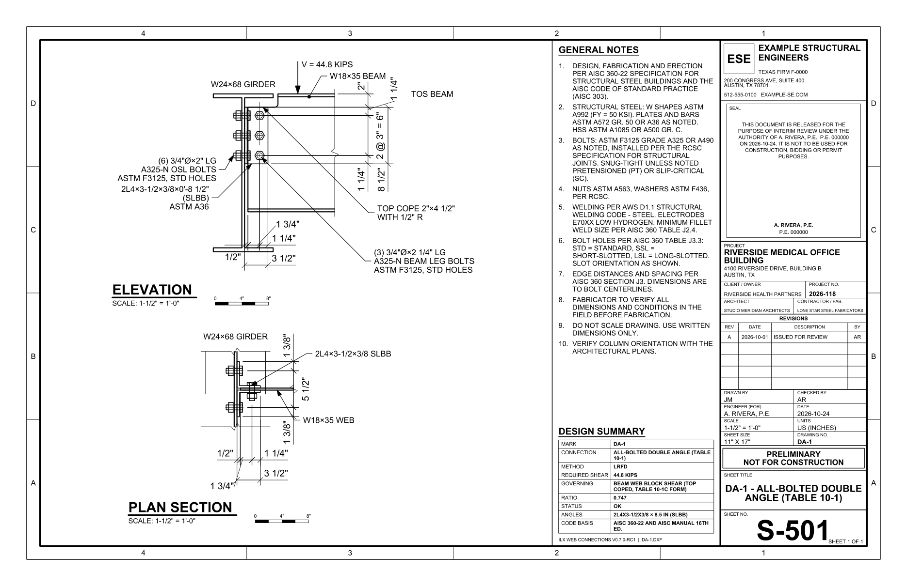
The drawing sheet carries the elevation and the plan section with the title block. Section A-A is on screen and in the calculation report. See Drawings and Reports.
Auto-design, compare and batch #
Auto-design searches:
- the bolt diameter: 3/4, 7/8 or 1 in., when there are bolts;
- the angle: 13 standard angles from L3X3X1/4 to L6X4X5/8, lightest first;
- the number of rows: from the smallest count that reaches T/2 up to 12. For the all-welded configuration, it searches the angle length in 1-1/2 in. steps instead;
- the sizes of Welds A and Welds B: 3/16 to 3/8 in., no larger than t − 1/16 in.
For each angle, it keeps the shortest length that passes. It never changes the configuration, the members or the support. Pinned fields are kept. The objectives are Lightest (steel weight), Fewest bolts and Lowest cost (fabrication estimate). For the dialog, see Auto-design, compare and batch.
Compare works for double angles. The default batch columns are beam, support, RD and RL. When batch auto-designs, it keeps the beam, the support, the support type and the configuration.
Limitations and documented deviations #
Scope
- The beam is a W, M, S or HP shape. The support is a W, M, S or HP shape, or a rectangular HSS (outstanding legs welded, or bolted with through-bolts or blind bolts; no axial tension when bolted).
- Each leg takes 1 or 2 bolt lines, with 1 to 20 rows.
- Back-to-back connections (shared or staggered) need a column or girder web and bolted outstanding legs.
Simplifications
- The outstanding-leg bolts carry the shear only. Axial tension goes to bolt tension with prying, and compression to bearing of the legs on the support (Design Example II.A-2B).
- The eccentricity on the beam-leg bolts is neglected unless you tick the IC option, and only where Manual p. 10-10 permits it (one bolt line, STD or short-slotted holes, a ≤ 3 in.).
- The Welds B return is not counted in the strength. The axial interaction of Welds B is engineering practice, not a Manual equation. Out-of-plane bending of the outstanding legs about the toe welds is covered only by the flexibility note.
- The girder web yield line and the HSS plastification under axial load are approximate. Both are flagged in the check.
- The tightening clearance C1 and fillet clearance C3 come from Manual Table 7-15 (Table 7-16 for F1852 and F2280 twist-off bolts, with the tool and socket set in Settings > Design rules; 1/2 in., Group 200 (F3043), A307 and threaded-rod bolts use your C1 from the same tab, as the Manual does not tabulate them). The staggered-bolt clearance on both sides of a web is your input, with the ILX approximation as the default: the Manual's staggered-bolt tables cover bolts in the two legs of an angle.
- Letter-size sheets can overflow with the text-dominated views. Use 11 × 17.
Verification. ILX matches 124 published LRFD and ASD values of Design Examples II.A-1A, 1B, 1C, 2A, 2B, 3, 4, 5, 8 and K.3 within 0.81 %. Other rows of Tables 10-1 to 10-3 were not benchmarked. See Verification.
Documented deviations
| Example | Published | ILX | Why |
|---|---|---|---|
| II.A-2B, Welds A | 175.5 kips (Table 8-8 entered at 30°) | 180.2 kips (+2.7 %) | ILX uses the actual load angle, 38.7°. The example rounds down to the 30° table row, which is conservative. At 30°, ILX gives C = 2.689, as the table does. |
| II.A-1B, block-shear interaction | 0.0531 (with the larger L-shape axial block) | 0.0543 | ILX combines the shear block with the smaller of the U-shape and L-shape axial blocks, which is conservative (+2.3 %). |