
Designing an FR moment connection
A fully restrained (FR) moment connection transfers the beam end moment to the column through the beam flanges, and the shear through the web. ILX designs the three FR connections of AISC Manual Part 11 to AISC 360-22, with the column checks of J10 and the stiffeners and doublers they require.
When to use an FR connection #
Use it for a beam framing into a column flange where the joint must carry moment: wind or gravity frames, R = 3 systems designed to AISC 360 only, and seismic moment frames (OMF, IMF, SMF) designed to AISC 341-22 with the AISC 358-22 prequalified connections (see Seismic moment frames).
- Bolted flange plates: plates shop-welded to the column, field-bolted to the beam flanges (Design Example II.B-1).
- Welded flange plates: plates shop-welded to the column, field fillet-welded to the beam flanges (II.B-2).
- Directly welded: beam flanges CJP groove-welded to the column flange (II.B-3).
For an IMF or SMF, the directly welded connection is designed as the reduced beam section (RBS, 358-22 Chapter 5) or the welded unreinforced flange-welded web (WUF-W, Chapter 8), and the bolted flange plates as the bolted flange plate (BFP, Chapter 7). Welded flange plates have no prequalified connection and stay flagged as not adequate. For a simple shear connection, use Designing a single-plate connection.
Creating an FR connection in the wizard #
The wizard has three steps: Connection, Members and Loads.
- Connection. Under Connection type, in the Moment group, select FR moment. There is no joint-type choice: the beam frames into the column flange.
- Under FR moment connection (Manual Part 11), select one of the three cards. Each sets the Connection field of the editor:
Card Sets Description Bolted flange plates Bolted flange plates Plates welded to the column, bolted to the beam flanges (II.B-1) Welded flange plates Welded flange plates Plates welded to the column and fillet-welded to the beam (II.B-2) Directly welded flanges Directly welded CJP groove-welded beam flanges, bolted shear tab (II.B-3)
- Members. Enter the Connection mark (MC-1, MC-2 and so on by default), the Beam and the Column. Both are W shapes.
- Loads. Enter the service moments Dead MD and Live ML (kip-ft) and the service shears Dead VD and Live VL (kips). The wizard notes that Column stiffeners and doublers are designed automatically when required (AISC 360 J10). Use the editor for the other load modes, axial load, the opposite beam and the column forces.
- Optional: tick Auto-design the connection (flange plates, bolts, welds) for these loads. ILX sizes the hardware before it creates the connection, keeping the beam, column and connection kind (see Auto-design, batch and compare). A notification gives the result: adequate or best effort, with the ratio.
- Select Create.
The wizard always creates the connection in US units. Switch to Metric in the editor toolbar afterwards if needed.
Inputs by section #
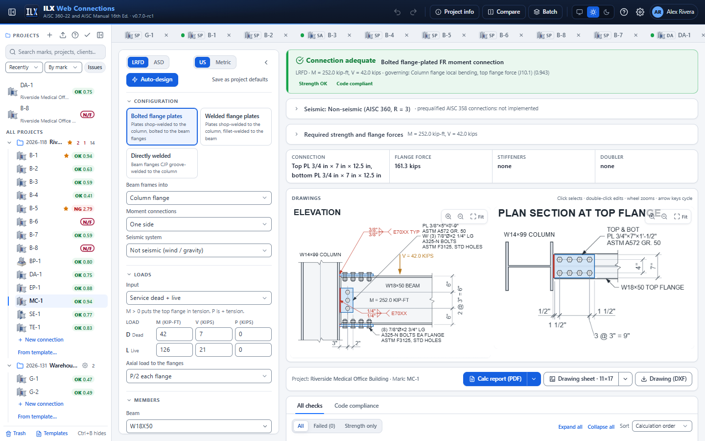
The toolbar has Design method (LRFD or ASD), Units (US or Metric), Auto-design and Save as project defaults. The last one saves this type's materials, hardware and methods as project defaults; members and loads are not saved.
Above the drawings, the key data strip shows the Connection (the plates or CJP flanges), the Flange force, the Stiffeners and the Doubler. Open Required strength and flange forces to see the combination and the flange forces worked out.
FR configuration and scope #
| Field | Options and notes |
|---|---|
| Configuration buttons | Bolted flange plates, Welded flange plates, Directly welded |
| Beam frames into | Column flange, or Column web (advisory only). The column-web case is not designed: it adds a failing scope check and the beam-side checks assume a column flange. |
| Moment connections | One side, or Both column flanges (adds the opposite beam and its moment M2) |
| Seismic system | Not seismic (wind / gravity), R = 3 (AISC 360 only), OMF (AISC 341-22 E1), IMF (AISC 341-22 E2, AISC 358-22), SMF (AISC 341-22 E3, AISC 358-22) |
For OMF, IMF and SMF a Seismic (AISC 341-22 / 358-22) section opens below the configuration (see Seismic moment frames), and a Seismic card above the drawings shows the design basis (Mpr, Sh, Vh, Mf, Vu, the protected zone) and the status of each prequalified connection. With welded flange plates in an IMF or SMF the editor warns that the configuration is not a prequalified connection.
Moment, shear and axial loads #
Choose the load mode with Input. M > 0 puts the top flange in tension. P is positive in tension.
| Input | Enter | Combinations used |
|---|---|---|
| Service dead + live (default) | M, V and P for D and L | LRFD: 1.2D + 1.6L, or 1.4D when it governs. ASD: D + L. |
| Service components → ASCE 7 combinations | M, V and P for D, L, Lr, S, W and E | Every ASCE 7-22 LRFD (2.3) or ASD (2.4) combination, W and E with both signs; the envelope governs |
| Required strength (Mu, Vu, Pu) | Mu, Vu, Pu (+T) (Ma, Va, Pa in ASD) | None (used as entered) |
| Load cases (table) | Named cases with M, V and P; Add case adds a row | Each case is checked; the envelope governs |
- Moments are in kip-ft (kN-m), forces in kips (kN). V cannot be negative, except for W and E.
- With Both column flanges, an M2 column appears: the opposite beam's moment, + when its top flange is in tension.
- Axial load to the flanges: P/2 each flange or In proportion to area. With a welded web, P/2 is always used.
- Because W and E act with both signs, a reversing moment designs both flanges for tension and compression. The Load combinations table lists every combination (see Load combinations in the results).
Beam and column #
| Field | Notes |
|---|---|
| Beam, Beam material | W, M, S or HP shape; ASTM A992 and so on |
| Opposite beam | Both column flanges only. It uses the same connection type and plate sizes. |
| Column, Column material | W, M, S or HP shape |
| Beam setback | Column face to the beam end. For directly welded flanges it is also the CJP root opening on the drawing. |
Flange plates or flange welds #
The section is titled Flange plates, or Flange welds for directly welded flanges.
| Field | Shows for | Notes |
|---|---|---|
| Top plate t, Top plate width, Bottom plate t, Bottom plate width | Flange plates | 1/4 in. to 2 in. |
| Top plate length, Bottom plate length | Welded flange plates | Bolted plates take their length from the bolts: af + (n − 1) s + end distance |
| Flange plate material | Flange plates | |
| Plate to column | Flange plates | Fillet, both faces or CJP groove weld |
| Top plate fillet, Bottom plate fillet | Fillet to column | Fillet on each face of the plate |
| Bolts per row, Pitch | Bolted | Two rows of 1 to 12 bolts each |
| Gage (2 rows), Column face to 1st bolt | Bolted | af is measured from the column face |
| End distance (plate end), Beam underrun tolerance | Bolted (underrun also welded) | The underrun reduces the beam flange end distance and lengthens the unbraced plate |
| Holes in plates, Holes in beam flanges | Bolted | STD, OVS, SSL or LSL along the beam (∥ force) or across the flange (⊥ force) |
| Shim / filler | Bolted | Fillers over 1/4 in. reduce bolt shear (J5.2) |
| Top plate to beam fillet, Bottom plate to beam fillet | Welded flange plates | |
| Top weld length / side (0 = max), Bottom weld length / side (0 = max) | Welded flange plates | 0 uses all the length available on the plate |
| Beam end to start of weld | Welded flange plates | Part of the unbraced plate length in compression |
| Transverse weld at the end of a narrower plate | Welded flange plates | Adds the end weld when the plate is narrower than the beam flange |
| K, plate in compression | Flange plates | Default 0.65 |
| CJP backing | Directly welded | Left in place or Removed + reinforcing fillet |
| Reinforcing fillet | Backing removed | |
| Access hole length, Access hole height, Access hole radius | Directly welded | The J1.6 weld access hole in the beam web |
Flange and web bolts #
The Bolts section appears when there are bolts: bolted flange plates, or a web plate. The same bolts are used in the flange plates and the web plate.
| Field | Options |
|---|---|
| Bolt grade | The bolt grades of the bolt library |
| Bolt diameter | The sizes allowed for the grade |
| Threads | Included (N) or Excluded (X) |
| Joint | Bearing (snug / pretensioned) or Slip-critical |
| Surface (slip-critical) | Class A (μ = 0.30) or Class B (μ = 0.50) |
| Hole deformation is a design consideration (2.4 / 1.2) | Cleared: 3.0 and 1.5 (J3.11) |
Web shear connection #
| Field | Shows for | Notes |
|---|---|---|
| Web connection | Always | Single plate bolted to the web or Beam web welded to the column |
| Web plate design | Web plate | Direct shear (flanges absorb eccentricity, II.B-1) (default) or Single-plate procedure (Part 10) |
| Web plate t, Web plate material | Web plate | |
| Bolts, n, Spacing, s | Web plate | 2 to 20 bolts in one vertical row |
| Lev, plate, Top of beam to plate (0 = centred) | Web plate | |
| Weld line to bolts, a, Leh, plate | Web plate | |
| Plate holes, Beam web holes | Web plate | STD, OVS, SSL, LSL |
Direct shear follows Design Example II.B-1: the flange connections absorb the eccentricity, so the web bolts and weld are checked concentrically and the Part 10 simple-connection rules are dropped. Single-plate procedure (Part 10) runs the full single-plate design instead.
Welds to the column flange #
| Field | Shows for | Notes |
|---|---|---|
| Web plate fillet (both sides) | Web plate | Plate to column flange |
| Web weld | Welded web | Fillet, both sides or CJP |
| Web fillet | Welded web, fillet | |
| Electrode | Always | E70XX or E80XX |
Column stiffening (J10) #
The Column (J10) section holds the column forces and the stiffener and doubler options.
| Field | Notes |
|---|---|
| Column axial Pu (compression +) | Required column axial strength (Pa in ASD), for α Pr / Py in J10.6 |
| Column story shear Vu | Reduces the panel-zone shear |
| Column ends at this connection (roof) | Applies the end-of-member reductions of J10.1 to J10.5 |
| Column top to top of beam | Shows when the column ends here. Each check states the distance to the flange force and the equation it selects: J10.1 halved within 10tf, Eq. J10-3 within d, Eqs. J10-5a/b within d/2 |
| Analysis includes inelastic panel-zone deformation (J10.6(b)) | Uses J10.6(b) in place of J10.6(a) |
| Transverse stiffeners | Design when required (default), Provided (as entered) or None |
| Stiffener t | Provided only; otherwise designed |
| Stiffener width (0 = max), Stiffener length | Full depth or Half depth |
| Corner clip (min.), Stiffener fillets (min.), Stiffener material | With Design when required, the clips and fillets are increased as needed |
| Compression stiffeners finished to bear | Fitted bearing, minimum welds to the flange |
| Web doubler | Design when required (default), Provided (as entered) or None |
| Doubler t | Provided only; otherwise designed |
| Doublers | One side of the web or Both sides |
| Doubler to flanges, Doubler fillet (min.) | Fillet or CJP |
| Doubler extension past the flange forces, Doubler material |
With Design when required, ILX adds stiffeners when any of J10.1 to J10.5 fails and a doubler when J10.6 fails, and proposes the designed sizes as suggested fixes.
Seismic moment frames (AISC 341-22 / 358-22) #
ILX follows AISC 341-22 Chapter E and AISC 358-22 as written. Where they leave a value or a choice to you, it is an input with a stated default, and the calculation report states it. You are the engineer of record.
Which connection is designed
| Seismic system | Connection | Design |
|---|---|---|
| IMF, SMF | Directly welded, Welded flange connection (AISC 358-22) = Reduced beam section, RBS (Chapter 5) | 358-22 Chapter 5 |
| IMF, SMF | Directly welded, WUF-W (Chapter 8) | 358-22 Chapter 8 |
| IMF, SMF | Bolted flange plates | Bolted flange plate (BFP), 358-22 Chapter 7 |
| IMF, SMF | Welded flange plates | Not prequalified: a failing scope check |
| OMF | Any, with OMF connection (AISC 341-22 E1.6b) | (a) required flexure 1.1 Ry Mp / αs and shear from Ecl = 2(1.1 Ry Mp)/Lcf; (b) the maximum moment and shear the system can deliver, entered; (c) the prescriptive welded details (directly welded flanges only); or an AISC 358 connection as for an IMF |
The AISC 358-22 procedures are LRFD whatever the design method (358-22 1.3); the column checks at the probable flange force use Pf / αs in ASD. OMF (a) and (b) work at the design-method level (αs = 1.5 in ASD).
Inputs (section Seismic (AISC 341-22 / 358-22))
| Field | Default | Notes |
|---|---|---|
| OMF connection (AISC 341-22 E1.6b) | (a) | OMF only |
| Welded flange connection (AISC 358-22) | RBS | Directly welded flanges in an IMF / SMF |
| Clear span between column faces, Lcf | 360 in. | Span-to-depth limit, Lh = Lcf − 2 Sh, and Ecl for an OMF |
| Gravity line load wu (1.2D + f1L + 0.15S) | 1.25 kip/ft | Factored, on the beam between the hinges (358-22 2.4.4); f1 not less than 0.5 |
| Further gravity shear at the hinge | 0 | Concentrated loads, same combination |
| Cpr (0 = AISC 358-22 value) | 0 | (Fy + Fu)/(2Fy) ≤ 1.2 (Eq. 2.4-2); 1.4 for WUF-W (8.6). A value entered overrides the standard |
| Moment connection at this end only (far end pinned) | off | Vh = Mpr / (Lcf − Sh) + Vgravity (2.4.4 User Note) |
| Maximum moment by the system, Corresponding shear | 0 | OMF (b) |
| Beam Ry, Beam Rt | 0 | 0 = AISC 341-22 Table A3.2 (A992 and A572 Gr. 50 shapes 1.1 / 1.1, A36 1.5 / 1.2) |
| RBS a, RBS b, RBS c | 0 (auto) | Auto: a = 0.625 bf and b = 0.75 d to 1/4 in., c the smallest 1/8 in. from 0.1 bf with Mf ≤ φd Mpe; the values are offered as suggested fixes so you can keep them |
| Concrete structural slab, shear studs at 12 in. max. | on | The chapter's exception to supplemental bracing at the hinge; BFP column depth W36 (W14 without a slab) |
| Slab isolated from the column (358-22 2.3.4) | off | BFP in an SMF with a slab |
| A moment-ratio exception of AISC 341-22 E3.4a applies | off | Eq. E3-1 becomes information |
With the WUF-W, and the RBS in an SMF, the web connection is the one 358-22 prescribes and the Web connection section shows its single plate: Single plate t (at least tw for WUF-W, 3/8 in. for RBS), Single plate width (0 = auto) (setback + access hole + 2 in.), Plate overlap with each access hole (1/4 to 1/2 in., WUF-W) and Single plate to column (fillets or CJP). An IMF RBS may keep the bolted single plate (5.5(2) Exception). The CJP backing has a third option, Bottom removed, top left (358-22 3.3).
What is checked
- Capacity design (358-22 2.4, 2.5): Mpr = Cpr Ry Fy Ze, Sh, Lh, Vh = 2 Mpr / Lh + Vgravity, Mf = Mpr + Vh Sh, Vu = Vh + wu Sh, shown under Required strength and flange forces and in the report.
- Prequalification limits of the chapter (beam depth, weight, flange thickness, clear span-to-depth ratio, column depth, rolled W shapes) and the width-to-thickness ratios of Table D1.1b (highly ductile for an SMF, moderately ductile for an IMF; RBS flange width at the ends of the centre two-thirds).
- RBS: a, b, c within Eqs. 5.7-1 to 5.7-3, ZRBS (Eq. 5.7-4), Mf ≤ φd Ry Fy Zb (Eq. 5.7-7), the reduced section for the load combinations, the web (CJP or the IMF bolted plate with its slip-critical, J3-6a, holes and 5/8 tp fillet rules).
- WUF-W: Cpr = 1.4, Sh = 0, the single plate (thickness, overlap, width, welds for 0.6 Ry Fyp hp tp, fillet tp − 1/16), the AWS D1.8 access hole (length 3 tbf ± 1/2 in., height 3/4 tbf to tbf, radius 3/8 in.).
- BFP: plates, bolts and holes of 7.4, Eq. 7.5-1 (net section), the bolts (Eq. 7.5-7), plate yielding, rupture, block shear (plate and beam flange) and buckling (Eqs. 7.5-8 to 7.5-11, KL = 0.65 S1 by default through K, plate in compression), lc ≥ 2 db, and the web plate for Vu.
- Beam shear at Vu (G2.1), the CJP web at Vu, 358 Chapter 3 backing and reinforcing fillet, demand-critical welds.
- Continuity plates (AISC 341-22 E3.6f): required when the column J10 limit states fail at Pf = Mf / (αs d*) (0.85 Mf with a welded web) or tcf < bbf/6 (Eq. E3-7); then their thickness, b/t (Eq. E3-9), width, welds and the 358-22 3.6 corner clips. With Design when required the plates are sized to meet them.
- SMF panel zone (E3.6e): Σ Mf / db − Vc with φv = 1.00, the doubler, Eq. E3-6 for the web and the doubler, the doubler welds (groove welds in practice) and extension. IMF and OMF use the J10.6 check with the load combinations (E2.6e, E1 User Notes).
- SMF column-beam moment ratio (Eq. E3-1), column bracing (E3.4c), beam bracing and the protected zone, as notes with their values.
Not built: the extended end plates of 358-22 Chapter 6 (BUEEP / BSEEP, the next step with the end-plate moment connection), the double tee (Chapter 13) and the slotted web (Chapter 14).
Checks the FR connection runs #
Every check is run for every load combination and the governing one is reported. See Checks and compliance for reading the results.
Flange force. Puf = M / dm + Pf (Manual Eq. 11-1). dm is taken per element, as in the Design Examples: the beam depth d for the bolts and the plate-to-beam welds, d + tp,top/2 + tp,bot/2 for the plates, the plate-to-column welds and the column, and d − tf for directly welded flanges.
Beam.
- Flexural yielding at the connection, Mp (AISC 360-22 F2.1).
- Tension flange rupture at the bolt holes (AISC 360-22 F13.1), bolted flange plates.
Bolted flange plates.
- Flange bolts: shear, bearing and tearout in the plate and the beam flange, summed per bolt (AISC 360-22 J3.7, Table J3.2; AISC 360-22 J3.11), with the long-joint and J5.2 filler reductions. Slip resistance (AISC 360-22 J3.9) when slip-critical.
- Flange plate: tensile yielding (J4.1(a)), tensile rupture (J4.1(b)), block shear rupture (J4.3, three failure paths), compression (J4.4) with Lc = K max(af, s).
- Beam flange block shear rupture (J4.3).
- Detailing: pitch and gage ≥ 2⅔d (J3.4, 3d preferred), edge and end distances (J3.5, Table J3.4), maximum spacing and edge distance (J3.6), tightening clearance and bolt seat clear of the web fillet (Manual Part 7), slip-critical bolts required for OVS holes or slots parallel to the force (J3.3), a pretension recommendation for bearing bolts and a shim note (Manual Part 11).
Welded flange plates.
- Flange plate tensile yielding (J4.1(a)) and compression (J4.4), with L = setback + underrun + start of weld.
- Plate-to-beam fillets (AISC 360-22 J2.4(c), Eq. J2-6), with the size limits (J2.2b, Table J2.4), l ≥ 4w, l ≥ the distance between longitudinal welds, and the end-loaded β note.
- Base metal ≥ 3.09D/Fu (Manual Part 9) and beam flange shear rupture at the welds (J4.2(b)).
Plate to column. Fillets on both faces (AISC 360-22 J2.4, Table J2.5) with minimum and practical maximum sizes, or a CJP groove weld that develops the plate.
Directly welded flanges.
- CJP groove weld, base metal governs: Fy bf tf (AISC 360-22 J2.4, Table J2.5).
- Matching filler metal (recommendation), beam flange within the column flange width, backing note.
- Weld access holes (AISC 360-22 J1.6): length ≥ 1.5 tw and ≥ 1½ in., height ≥ tw and ≥ ¾ in. (need not exceed 2 in.), radius ≥ ⅜ in., finish note.
Web connection.
- Web plate, direct shear: bolts (J3.7, J3.11) and the fillet welds to the column (J2.4), concentric, plus the single-plate engine's plate, beam web and column flange checks, shown as Web plate: … and Web connection: ….
- Web plate, Part 10: the full single-plate design.
- Welded web: fillet welds both sides (J2.4), web base metal ≥ 6.19D/Fu (Manual Part 9), minimum size, or a CJP note; beam web shear yielding along the weld (J4.2(a)).
Column (J10). For each flange force, and for the opposite beam's:
- Flange local bending (AISC 360-22 J10.1), tension forces; not required when the loaded width is < 0.15 bf.
- Web local yielding (J10.2).
- Web crippling (J10.3), compression forces.
- Web compression buckling (J10.5), only with beams on both flanges in compression at the same level.
- Web panel-zone shear (J10.6), Vr = ΣPuf − Vc, by J10.6(a) or (b).
Stiffeners (AISC 360-22 J10.8). Width + tw/2 ≥ b/3, thickness ≥ t/2 of the loading plate or flange and ≥ width/16, length ≥ ½ depth (¾ for crippling, full depth for J10.5), tension or compression strength (compression as a column with a 25tw web strip, Lc = 0.75h), flange and web welds, column web shear rupture along the welds, and corner clips that clear the column fillets (Manual Part 4 / AISC Design Guide 13).
Doublers (AISC 360-22 J10.9). Panel-zone shear with the doubler (t = tw + Σtd, Fy = the lower of column and doubler), doubler-to-flange welds for the doubler's share of the shear, fillet ≤ td − 1/16 or CJP, and recommendations from Manual Part 4 / Design Guide 13: thickness ≥ (dz + wz)/90, extension ≥ 6 in. past the flange forces without stiffeners, k-region clearance.
NOT FEASIBLE is reported when the geometry cannot be built: the first flange bolt off the beam, bolt rows that do not fit the plate or flange, a plate or beam flange wider than the column flange, no shelf for a fillet, a weld longer than the plate, an access-hole radius larger than its height, or a stiffener wider than the column flange outstand.
Fatigue (Appendix 3). The Cyclic loading (fatigue) section designs the connection for fatigue: the cycle count nSR and the cyclic range as a fraction of the live moment ML or as the moment range entered (see Fatigue (Appendix 3)). The flange force range is the flange force at the governing moment times the range ratio. The details: directly welded flanges, the CJP weld to the column (Table A-3.1 Case 5.4, C; Eq. A-3-1 applies only to CJP welds tested per Section 3.6, an engineer setting, see Settings) and the beam web at the weld access holes (Case 1.4: C for R ≥ 1 in. ground, else E′); flange plates, the plate at its fillets to the column (Case 5.7, C and C″ with RFIL) and those fillets (Case 8.2, F), or the CJP weld (Case 5.4); bolted plates, the plate and the beam flange at the bolt holes (Section 2, or Case 1.5 for snug-tight joints); welded plates, the plate and the beam flange at the ends of the longitudinal welds (Case 4.1, E for t ≤ 1/2 in., E′ above) and the plate-to-beam fillets (Case 8.2); the web shear tab as a single plate.
FR drawings, report and sheet #
The editor draws two views:
- ELEVATION: the column in side view with the stiffeners at the flange force lines and the doubler face-on; the beam with its flange plates (flange bolts in side view, or plate-to-beam fillets) or CJP flange welds with backing bars or reinforcing fillets and the access holes; the shear tab with its bolts or the welded web; dimension chains, V and M.
- PLAN SECTION AT TOP FLANGE: the column section cut at the top flange, with the stiffeners, corner clips and doubler, the beam top flange, the flange plate and its bolt pattern.
In a seismic design the elevation hatches the protected zone on both beam flanges and notes its length from the column face, the plan shows the RBS radius cut with a and b in the dimension chain and a callout of c and R, and the elevation draws the WUF-W single plate (1 in. straight at the column, 30° slopes) or the RBS backing plate over the CJP web weld. The access-hole note cites AWS D1.8 where the connection requires its geometry, and a bottom-only backing removal gives one weld symbol per flange (R at the bottom, B at the top).
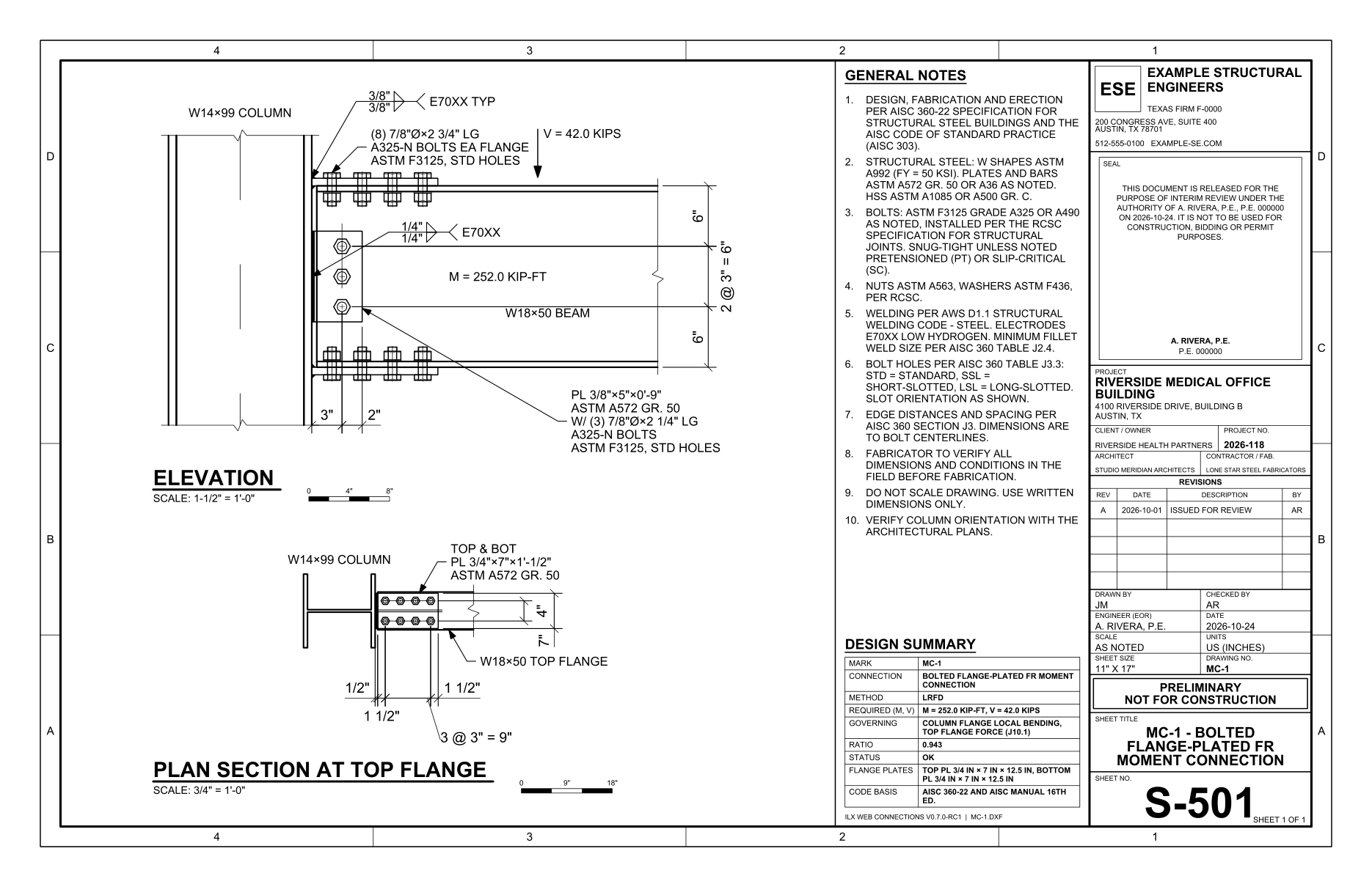
The sheet carries the same two views and the shared sheet content (see Drawing sheets). Its weld symbols follow AWS A2.4:
- CJP beam flanges: single-bevel groove symbol with the joint designation TC-U4a in the tail, backing B (left in place) or R (removed, with the reinforcing fillet), and the field-weld flag.
- Flange plates to the column: fillets on both sides, or a single-bevel CJP with backing.
- Flange plates to the beam: field fillets marked 3 SIDES with the transverse end weld, or BOTH SIDES.
- The shear tab, the welded web, the stiffeners and the doublers.
Each bolt group has one callout with its own bolt length: the flange bolts in the plan, the web bolts in the elevation. See Weld symbols and Drawings. The calculation report lists the inputs (configuration, members, seismic basis, loads, plates, bolts, welds, stiffeners and doubler) and every check; see Reports.
FR auto-design, batch and compare #
Auto-design uses the shared dialog described in Auto-design, compare and batch. For FR connections it never changes the members, the loads, the connection kind, the joint, the stiffener and doubler options or the geometry rules (pitch, gage, edge distances, setback). It sizes the hardware only, from the lightest up:
| Connection | What it searches, in order |
|---|---|
| Bolted flange plates | For each bolt diameter (3/4, 7/8 and 1 in., shared with the web bolts): the fewest bolts per row (2 to 10), the lightest plate width × thickness (both plates alike; widths from the current width, the beam flange width and the flange width + 1 in.), then the smallest plate-to-column fillet |
| Welded flange plates | For each flange: the thinnest plate, then the smallest plate-to-beam fillet (the plate lengthened in 2 in. steps when the weld is too short), then the smallest plate-to-column fillet |
| All, with a web plate | The fewest web bolts (2 to 12), the thinnest web plate, the smallest fillet to the column |
For directly welded flanges only the bolt diameter and the web plate are searched; the CJP welds need no sizing. Stiffeners and doublers are designed by the calculation itself.
A design is listed only when every non-advisory check passes. When no hardware can pass (for example the beam fails F13.1), the closest design is shown. The objectives are Lightest (steel weight), Fewest bolts and Lowest cost (fabrication estimate). The wizard's auto-design keeps beam, column and conn, and uses the lightest objective.
Batch design pastes a schedule of marks with the columns mark, beam, column, MD, ML, VD and VL. Auto-design each mark is available. Compare works as for the other types.
PR moment connections: column stiffeners and doubler #
The PR moment connection (top and seat angles, Manual Part 11) checks the same column limit states at the angle force lines: web local yielding at both angles (J10.2), web crippling at the compression angle (J10.3), the column flange in bending through the tension-angle bolts (prying, Manual Part 9) and the panel zone (J10.6). Its Column reinforcement (J10.8, J10.9) section offers the FR options:
- Column stiffeners at the angles: None (default; saved connections are unchanged), Design when required or Provided (as entered), with the same thickness, width, length, clip, fillet, material and finished to bear fields as above. A pair is placed at each angle force line (the faying surfaces, or the angle-leg centrelines with that lever arm) where J10.2 / J10.3 fail. It carries Ru − φRn of the governing limit state (the FR rule) and its strength is added to those checks (with stiffeners). The angle length and thickness are the delivering plate for J10.8(a) and (b). A recommendation checks that the column-leg bolts inside the column flange clear the stiffener (tightening clearance).
- Panel-zone web doubler: None (default), Design when required or Provided, with doublers on one or both sides, fillet or CJP edges and an extension past the angle forces. Panel-zone shear with the doubler (J10.6, J10.9) and its welds, and the Manual Part 4 / Design Guide 13 recommendations, as for the FR connection.
Two PR inputs are engineering choices that the Manual leaves to you, so set them:
- Flange-force lever arm (Configuration): the beam depth d or the distance between the angle-leg centrelines. Manual Eq. 11-1 does not fix dm for flange angles. The Kishi-Chen moment-rotation model always rotates about the seat-angle leg, with a lever arm of d + tt/2 + ts/2.
- Column ends near the joint (Spec. J10.2, J10.3) and Column top to top of beam (Members): cleared (default), the column is not near its end and the checks use Eqs. J10-2 and J10-4. Ticked, the top-angle force is taken at the top of the beam and the seat force d lower; web local yielding uses Eq. J10-3 at an angle within d of the column end, and web crippling Eqs. J10-5a/b within d/2. The report states the distance and the equation.
- Column J10.2/J10.3 bearing length lb (Members): this is the bearing length at the column face that web local yielding and crippling use at each angle. The default 0 uses each angle's thickness. The calculation shows which value was used.
The moment-rotation curve and the B3.4b classification use the Kishi-Chen power model. The initial stiffness Rki and the capacity Mu come from Kishi and Chen (1990), ASCE Journal of Structural Engineering 116(7). Those equations use the seat angle's own thickness and length and the web angles' position on the beam web. The shape parameter n comes from Kishi, Chen, Goto and Matsuoka (1993), AISC Engineering Journal 30(3), Table 1. The 1993 paper restates the 1990 equations for equal top and seat angles with the web angles centred on the beam depth, and gives the same values there. The model is for angles bolted to the beam. If the angles are welded to the beam, the Kishi-Chen model scope check fails and the curve carries a note. The classification is then not valid for that connection. To get a valid classification, use bolted angles or establish the moment-rotation curve another way.
The stiffeners do not change the column-flange prying check at the tension-angle bolts (a conservative omission). The PR drawings show the stiffeners edge-on and the doubler face-on in the elevation, and the top stiffener pair with its clips in the plan section.
The B3.4 strength recommendation compares the moment at a rotation of 0.02 rad with 0.2 Mp. The Commentary takes the strength at 0.02 rad when the curve has no peak, and the power model has none. Without web angles, a Shear connection recommendation is shown. The Manual's flange-angle PR connection includes a simple shear connection (p. 11-27). Without web angles, the seat carries the reaction, checked with a simplified Part 10 unstiffened-seat model.
PR moment connections: flange plates #
The PR type also designs flange-plated PR connections (Manual pp. 11-28 to 11-30, Figs. 11-23 and 11-24). Select Flange connection → Flange plates, bolted to the beam or Flange plates, welded to the beam. In the wizard, use the two flange-plate cards. In this connection, top and bottom flange plates are welded to the column flange and bolted or welded to the beam flanges, and a single shear plate carries the shear.
Strength. The Manual takes the strength from the bolt, weld and connecting-element limit states of Parts 7, 8 and 9, and the FR flange-plate shop and field practices apply. ILX therefore runs the FR flange-plate checks described above for each load combination: flange bolts, plate tension, rupture, block shear and compression, beam flange block shear and F13.1, welds to the beam and to the column, and the column J10 checks with stiffeners and doubler. The flange-plate inputs (Flange plates (Manual Fig. 11-23) section) are the FR inputs. With the PR inputs set to the example geometry, the results reproduce Design Examples II.B-1 and II.B-2.
Unwelded length. The Manual says an unwelded length of 1½ times the plate width is "normally assumed to permit the elongation of the plate necessary for PR moment connection behavior". For welded plates, Unwelded length from the column (0 = 1½ bp) sets where the plate-to-beam welds start, measured from the column face. The default 0 uses 1½ bp for each plate. The welds run from there to the plate end, so the default plates are 18 in. long. This length is also the plate's unbraced length in compression. A shorter entered length gives an advisory recommendation. If no weld fits past it, the geometry is not feasible. The plan drawing carries the note "DO NOT WELD FIRST ... FROM COL". For bolted plates, the Manual gives no length. The calculation reports the free length from the column face to the first bolt, af, against 1½ bp.
Shear plate. Manual p. 11-29 calls the shear connection "a simple shear connection". Shear plate design defaults to Simple shear connection (Part 10), the full single-plate procedure with its eccentricity. Direct shear uses the FR assumption of p. 11-4 instead.
Moment-rotation curve (engineer input). Part 11 gives no moment-rotation model for flange plates. It only requires "a reliable moment-rotation, M-θ, curve" from tests, compilations or normalized curves (p. 11-26). B3.4b requires the curve to be "based on the technical literature or established by analytical or experimental means". Enter the curve under Stiffness and classification (B3.4b):
- M-θ curve: Linear, M = Ki θ (default; the linear model after shakedown, p. 11-26) or Power model (Ki, Mu, n), the same three-parameter form as the angle model.
- Stiffness Ki: kip-ft/rad (kN-m/rad). The default 0 means not entered.
- Curve moment Mu: required for the power model. For the linear curve it is an optional cap (0 = none).
- Shape parameter n: power model only (default 1.0).
- Source of the M-θ curve: the tests, literature or analysis the curve comes from. It is printed in the report.
Until Ki is entered, the Moment-rotation curve recommendation stays open and the connection is not classified. Once it is entered, the classification uses the same Commentary B3.4 rules as the angles: Ks = Ms/θs at the service moment, compared with 2EI/L and 20EI/L, and the moment at 0.02 rad compared with 0.2 Mp. The editor plots the curve. A recommendation notes that the curve must include the nonlinear and shakedown behavior (p. 11-26).
Drawings. The flange-plated configurations use the FR flange-plate elevation and plan. Welded plates show their welds starting past the unwelded length.
FR limitations and deviations #
Scope
- Seismic: RBS, WUF-W and BFP (AISC 358-22) and OMF E1.6b. Welded flange plates in an IMF / SMF and column-web joints are flagged not adequate; extended end plates (Chapter 6), double tees (Chapter 13) and built-up or box members are not designed. The AWS D1.8 access-hole geometry is taken from AISC Design Guide 21, Fig. 11-5 (D1.8 itself is not in the ILX library). The panel-zone story shear Vc is the Column story shear entered; plug-welded doublers are not designed.
- Column-web joints are advisory only: a failing check describes the Manual Part 11 detail, and the column is not designed.
- Beams and columns are W, M, S or HP shapes. The opposite beam uses the same connection type and plate sizes.
- Beam flexure is checked as Mp at the connection only. Lateral-torsional and flange local buckling belong to the member design.
Simplifications
- Diagonal panel-zone stiffeners are not designed; doublers only.
- The doubler is not credited in web local yielding (J10.2) or crippling (J10.3); the stiffeners carry those limit states.
- With beams on both sides, the stiffener-to-web weld force is the full stiffener force, not the difference of the two sides (conservative).
- Flange-plate bolts are in single shear without prying. In Direct shear, the web plate carries no moment (II.B-1).
- Bearing bolt values are used even when the pretension recommendation applies, as in Design Example II.B-1.
- The corner-clip, doubler-extent and (dz + wz)/90 rules are recommendations taken from the Design Guide 13 practice.
- The views are sized for the 11 × 17 sheet; on 8.5 × 11 portrait they may not fit, and an SMF design with continuity plates and a doubler needs 11 × 17 or larger.
Verification
ILX reproduces Design Examples II.B-1 (LRFD and ASD), II.B-2 (LRFD and ASD), II.B-3 and J.7:
- II.B-1: flange bolts, plate tension, rupture, block shear and compression, beam flange block shear, web plate, column J10.1 to J10.3 and F13.1 all within 0.4%; the flange forces (168 and 161 kips) are exact.
- II.B-2: within 0.6%. The beam flange shear rupture is 0.5% low because the Example rounds Anv.
- II.B-3: the Example refers the column checks to II.B-1. With dm = d − tf the flange force is 173.5 kips, just above the W14X99 flange local bending strength of 171 kips, so ILX designs stiffeners. This follows from the larger flange force of a directly welded connection; it is not a deviation.
- J.7: web local yielding and crippling within 0.1%.
See How ILX was verified.