
Designing a splice
ILX designs two kinds of splice:
- Beam shear splice. One or two plates join the webs of two beams at a point of contraflexure and carry the shear across the gap. Each side is bolted or welded.
- Compression splice. Flange plates on the outside of both flanges join two wide-flange members. Use it for a truss chord or strut, or for a column. The ends can be finished to bear or not.
Both editors work like the single-plate editor (see Designing a single-plate connection):
- the design reruns live;
- the status bar shows OK, NG or GEOMETRY NOT FEASIBLE;
- clicking a part in the drawing opens its fields;
- the Checks and Compliance tabs explain every result.
To start one, choose New connection and pick Beam shear splice or Compression splice (chord / column) in the first wizard step.
Beam shear splice #
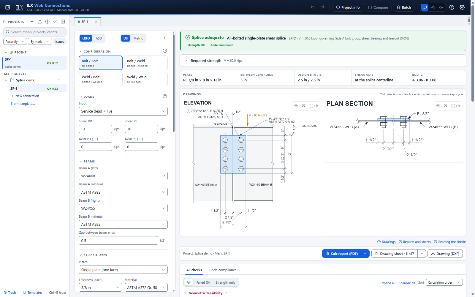
Configuration #
| Field | Meaning |
|---|---|
| Configuration | Bolt / Bolt, Bolt / Weld, Weld / Bolt or Weld / Weld. The first word is side A (beam A, on the left), the second side B. |
| Splice plates | Single plate on one face of the webs, or Two plates (both faces). With two plates the bolts are in double shear, and each plate is welded on its own face. |
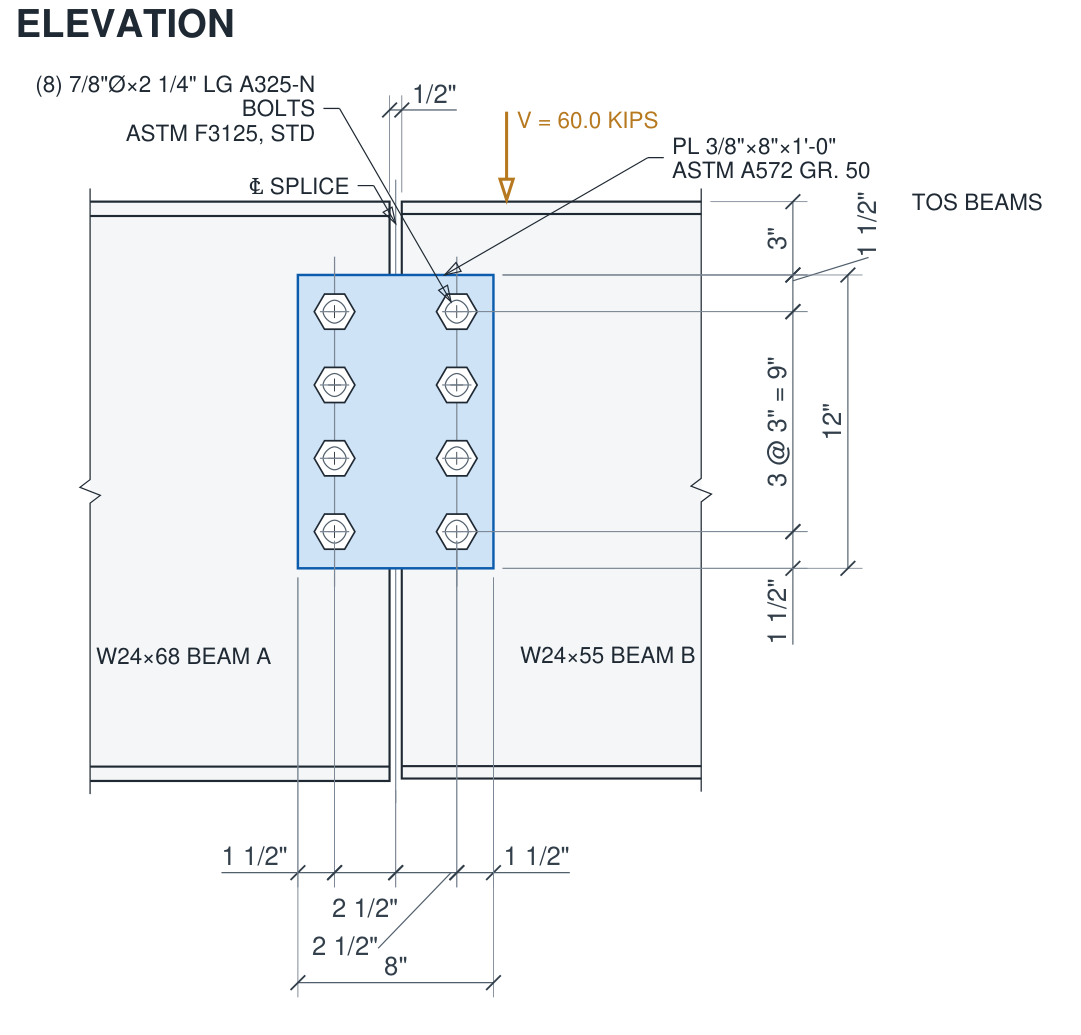
| Gap between beam ends | The clear distance between the beam ends. The splice centerline (℄ SPLICE in the drawing) is the middle of the gap. |
| Cb, plate lateral-torsional buckling (F11) (Splice plates) | Your input, default 1.84. The plate flexure check uses AISC 360-22 F11 with Lb = the gap. Neither the Manual (shear splices, pp. 10-68 and 10-69) nor Design Examples II.A-20 and II.A-21 (which use Mn = Fy Zx) give a Cb for a splice plate. 1.84 is the single-plate value of Manual Eq. 10-8. The report shows "Cb = x (engineer input)". |
| Beam A / Beam B | The two beams and their materials. Their tops are level. The beams may differ, as in AISC Design Example II.A-20 (W24X68 to W24X55). |
Loads on the shear splice #
Enter the shear across the splice and, if there is one, the axial force (+ tension). You can enter it in any of these forms:
- service dead and live loads
- a required strength
- ASCE 7 combinations
- your own load cases
The splice is assumed to sit at a point of contraflexure, so the moment at the splice centerline is zero.
Each side #
A bolted side has:
- Bolt rows (shared by both sides), spacing s and the plate's vertical edge distance Lev;
- the number of bolt columns and their gage;
- Centerline to first bolt column. The beam-end edge distance is this value minus half the gap.
- Plate edge distance beyond the last column.
A welded side has:
- the lap of the plate on the web, measured from the beam end;
- the weld size;
- the weld shape: C-shape, vertical only, or top and bottom.
The welds start at the beam end.
Eccentricity #
The shear does not pass through either connection, so each side is designed for a moment V × e. Eccentricity carried by sets how that moment is shared:
| Setting | Each side is designed for | Basis |
|---|---|---|
| Shear at the splice centerline | V at e = its centroid's distance from the centerline. On a symmetric splice this is half the distance between the groups. | Kulak and Green (1990); Design Example II.A-20 |
| Side A full / Side B full | That side takes the full distance between the two centroids; the other side takes shear only. | Design Example II.A-21: the more rigid weld group takes the full moment |
| Both sides full (conservative) | The full distance on both sides. | Conservative bound |
| Automatic (default) | Bolted / bolted: centerline. Bolted / welded: the welded side full. Welded / welded: both sides full. |
The plate is checked for flexure with the largest of these moments, as both AISC examples do.
What the shear splice checks #
| Element | Checks |
|---|---|
| Bolt groups | Instantaneous-center coefficient C at the design eccentricity and load angle. For each bolt, the least of shear, bearing and tearout in the plate(s) and the web. The shear is checked in both directions. Slip resistance applies when the joint is slip-critical. |
| Weld groups | Instantaneous-center strength of the weld shape at its eccentricity. Web and plate thickness needed to develop the weld (Manual Part 9). |
| Splice plate | Shear yielding and rupture, block shear, flexural yielding and rupture. Under axial load: tension yielding and rupture, axial block shear, compression buckling, and the Manual Part 12 interaction. |
| Beams | Web shear. If coped: net shear rupture, block shear, local flexural strength at the cope and rupture through the holes. Under axial tension: axial block shear, tension yielding and rupture. |
| Detailing | Spacing, edge distances (plate, beam ends, copes), maximum edge distance and spacing, wrench clearance to the flanges, hole and slip-critical rules, washers, weld sizes and lap, cope radius. |
Copes #
Turn on a top and/or bottom cope and choose which beam ends are coped (Coped beams: both, A or B). The cope length is measured from the beam end.
The coped-beam moment is taken from the cope face to the line of action of the shear. That line of action is never taken closer to the beam than the splice centerline.
Geometry not feasible #
The design is marked NOT FEASIBLE when any of these hold:
- the beam ends touch;
- the plate runs into the flange fillets or a cope;
- a bolt lies off the plate or the web;
- holes overlap;
- a cope removes the whole web;
- a weld has no web to sit on.
The message names the fix.
Compression splice (column or chord) #
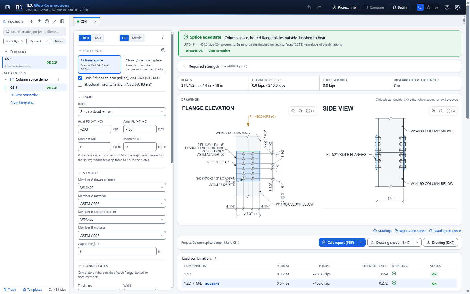
Splice type #
| Field | Meaning |
|---|---|
| Splice type | Column, a Manual Part 14 column splice, or Chord / strut, a compression member other than a column. |
| Finished to bear | The member ends are milled and in contact. Compression then passes in bearing, and the plates carry tension and hold the parts in line. When this is off, the plates and bolts carry the whole force, as in Design Example II.C-3. |
| Member A / Member B | The two members. When their depths differ, ILX places a filler of half the depth difference between the plate and the shallower member's flange. |
| Gap at the joint | 0 for a bearing joint. Up to 1/16 in. is permitted and gaps up to 1/4 in. are shimmed (AISC 360 M4.4). A larger gap is not feasible for a bearing splice. |
Loads on the compression splice #
Enter the axial force (+ tension) and the moment about the major axis at the splice, in one of these forms:
- service dead and live loads
- a required strength
- load cases
Each flange carries F = P/2 ± M/d, where d is the shallower member's depth.
For a column finished to bear:
- the plates are designed for the net flange tension from the load cases. A dead load that offsets the moment tension is taken into account.
- turn on Structural integrity and enter the nominal D + L tributary to the column below this splice to check AISC 360 B3.9(a). That check uses nominal strengths only.
- choose a Seismic column splice for a column of a seismic force-resisting system (AISC 341-22):
- SFRS column: D2.5. Enter the loads of the overstrength seismic load where they govern (D2.5b(a)). With the distance to the beam flange connection ILX checks the 4 ft rule of D2.5a (a clear height under 8 ft puts the splice at half of it). With the story height H the report gives the D2.5c shear Mpc / (αs H) about both axes. The flange plates carry no shear: splice the web with plates on both sides (D2.5d).
- Braced frame (SCBF, EBF, BRBF; F2.6d, F3.6d, F4.6d) adds a load case M = 0.5 Mp / αs of the smaller member with P = 0, and the shear Σ Mp / (αs Hc) with the clear height Hc.
- Special moment frame (E3.6g.5, bolted splices) adds a load case M = Ry Fy Zx / αs of the smaller column (Ry from Table A3.2) and the web splice shear Σ Mpc / (αs Hc).
- Every seismic splice checks the D2.2 bolted-joint rules: standard holes or short slots across the load, and pretensioned bolts with Class A (or better) faying surfaces.
For a chord finished to bear:
- enter the member length and the splice location;
- the flange plates are designed for the lesser of 50% of the compression as tension and the moment from a transverse load of 2% of the compression at the splice, with the member pinned (AISC 360 J1.4(b));
- the transverse shear is reported. Web splice plates are not designed.
Flange plates and bolts #
| Field | Meaning |
|---|---|
| Plate thickness, width, material | One plate on the outside of each flange. |
| Bolt lines per flange | 2, or 4 (with Outer line spacing). Inner gage is the distance between the two lines next to the web. |
| Side A / B bolt rows, spacing | Rows along the member on each side of the joint. |
| End distances | Plate end to the last row on each side, and each member end to its first row. |
| Effective length factor K | For the plate in compression between the rows nearest the joint. The default is 0.65, as in AISC Design Example II.B-1. |
| Fillers developed | Turn this on when the fillers are extended and developed. Otherwise fillers thicker than 1/4 in. reduce the bolt shear (AISC 360 J5.2). |
| Gusset section along the member, l and Holes on that section | Chord / strut only. Use them when the flange plates are the gusset plates of a truss panel point, as in Design Example II.C-3. l is the length of each plate's section along the member edge, through the bolt line; holes is the number of bolt holes on that line. ILX then checks the shear yielding and shear rupture of each plate on that section. Leave l at 0 for an ordinary splice. |
What the compression splice checks #
| Element | Checks |
|---|---|
| Bolts (per flange, each side) | The sum of each bolt's least of shear, bearing and tearout. Tearout runs toward the plate and member ends in tension and between the holes in compression. Slip resistance applies for slip-critical joints. |
| Flange plates | Yielding on the Whitmore section, gross yielding, net rupture, block shear (inner and outer blocks), and compression buckling across the joint. |
| Gusset section (chord, when l > 0) | Shear yielding, 0.60 Fy l t, and shear rupture, 0.60 Fu [l − n (dh + 1/16 in.)] t, of each plate along the member (AISC 360 J4.2), for the member force each plate carries. |
| Members | Flange block shear and tensile rupture at the holes (shear lag). |
| Bearing | Bearing on the milled surfaces (1.8 Fy Apb), a check that the flanges line up (otherwise a butt plate is needed), and the fit of the joint. |
| Detailing | Spacing and gage, plate and flange edge distances, maximum edge distance and spacing, clearance of the inner bolt line from the web fillet, hole and slip-critical rules, washers, and the erection load note for columns. |
AISC Manual Table 14-3 gives standard column splice details. Use them as the minimum for ordinary gravity columns.
Verification of the splice examples #
Both splice types reproduce the AISC Design Examples end to end, in LRFD and ASD:
- II.A-20, the all-bolted shear splice;
- II.A-21, the bolted and welded shear splice;
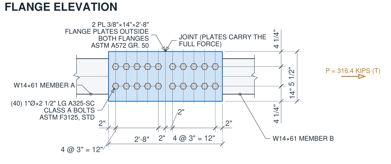
- II.C-3, each member-to-plate joint of the heavy wide-flange compression connection.
The comparison tables and the documented differences are on the Verification page (see Verification).
- II.A-21 weld length: AISC measures the short welds from the splice centerline; ILX uses the weld that can actually be placed, measured from the beam end. This is conservative, and with AISC's idealization ILX reproduces every published value.
- II.C-3 gusset shear: the shear yielding and rupture of the gusset plates along the chord (l = 32 in., 5 holes) and along the vertical (l = 31¾ in., 7 holes) are reproduced with the gusset section inputs. For the vertical, ILX gives 514 kips where the example prints 515, because the example rounds the net area.