
Designing a shear end-plate connection
A shear end plate is a plate shop-welded to the end of the beam web, with a fillet weld on each face of the web, and field-bolted to the support with two vertical lines of bolts. ILX designs it to AISC Manual Part 10, Shear End-Plate Connections (Table 10-4), and Design Examples II.A-11A to II.A-11C.
When to use a shear end plate #
- Use it when you want all the welding done in the shop and a simple bolted field connection, and the beam length can be held to the end-plate tolerance.
- The end plate must fit on the beam web flat, between the fillets or copes. A plate that projects past the beam flanges is an extended end plate, which is a moment connection, not this type.
- For a shear tab welded to the support, use the single plate. For a tab that is bolted on both sides, or when the beam length is uncertain, see double angles, the single angle and the shear tee.
Creating a shear end plate in the wizard #
- On the project row, open the menu (⋯) and choose New connection….
- Connection step:
- Connection type: Plate in the Simple shear group, then End plate under Plate type ("Plate shop-welded to the beam end, field-bolted to the support").
- Joint type: Beam to column flange, Beam to column web, Beam to girder web or Beam to HSS column. All four are offered. The cards read "End plate bolted to the support", or "End plate through-bolted to the HSS" for the HSS column.
- There are no configuration cards: the end plate is always welded to the beam and bolted to the support.
- Members step: Connection mark (prefix EP, for example EP-1), Supported beam, and Column, Girder or HSS column. Choosing the HSS joint changes the support to an HSS member.
- Loads step: Service D + L (Dead RD, Live RL) or Required strength (Shear Ru or Ra, and Axial (+T)). The other load modes are in the editor.
- Tick Auto-design the connection (bolt rows, end plate, weld) for these loads to size the connection before it is created. The beam, the support and the joint type are kept; the objective is the lightest design.
- Select Create.
Editor inputs #
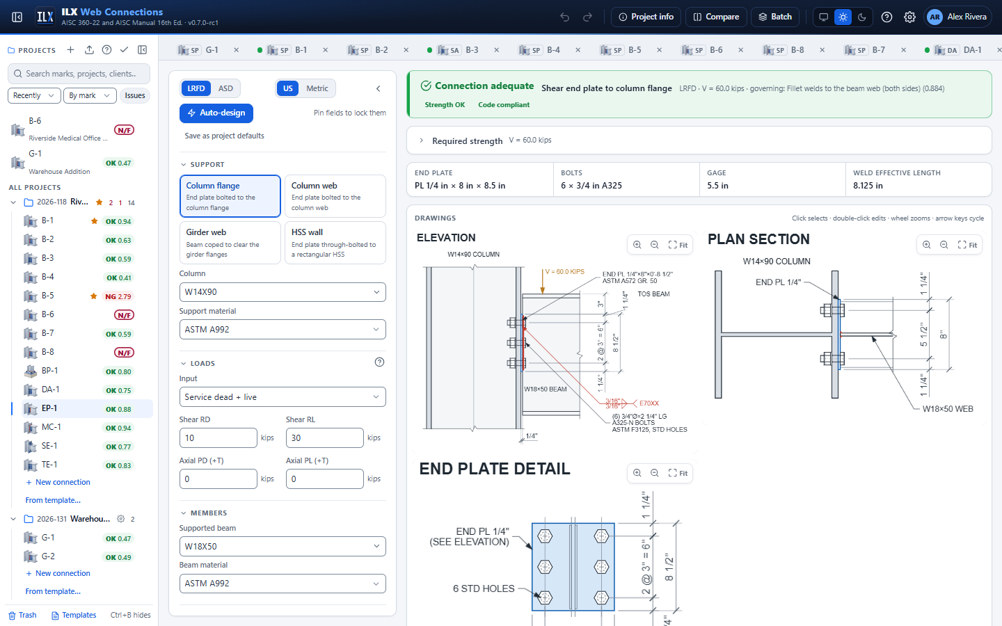
The toolbar has Design method (LRFD or ASD), Units (US or Metric), Auto-design and Save as project defaults. The key-geometry strip under the status bar shows the End plate (for example PL 1/4 × 8 1/2 × 8 1/2), the Bolts, the Gage and the Weld effective length per side.
The sections below follow the order of the input panel.
Support and framing #
| Field | Options and notes |
|---|---|
| Support cards | Column flange, Column web, Girder web ("Beam coped to clear the girder flanges"), HSS wall ("End plate through-bolted to a rectangular HSS") |
| Column, Girder or HSS column | The support member. Switching to HSS wall sets HSS8X8X1/2 in A500 Gr. C; switching back sets W14X90 (W24X68 for a girder) in A992. |
| Support material | HSS walls offer the A500, A1085 and A53 Gr. B grades only |
| Connected HSS face | HSS wall only: B or H face. Rectangular HSS only; the bolts pass through both walls. |
| Girder TOS − beam TOS (+ = beam lower) | Girder web only. Sets the bolt and plate position on the girder web and the flange interference check. Without a top cope, the editor reminds you that beams framing into a girder web usually need one. |
| Connections on both sides of the web | Column web and girder web only |
| Back-to-back end plates share the bolts | Shown when both sides are ticked. The bolts pass through both end plates and the web. |
| Connection near the column end, Column end to the connection force | Column web or column flange. Cleared (default): the connection is not near the column end. Ticked: enter the distance from the column end to the force. Column web: when it is less than √(8wab/(a + b)), ILX halves the Eq. 9-45 yield-line strength (Manual p. 9-18). Column flange with an axial force: web local yielding uses Eq. J10-3 when the distance is ≤ d, and web crippling Eqs. J10-5a/b when it is < d/2 (AISC 360-22 J10.2, J10.3). The report shows the limit, the distance and which equation was used. |
| Opposite connection shear (0 = same) | Shared bolts only. Sets this connection's share of the web bearing, V / (V + V other). |
Load modes and axial force #
All four load modes are available: Service dead + live, Service components → ASCE 7 combinations, Required strength and Factored load cases (table). Axial load is supported, positive in tension. See Loads and load combinations.
- Axial tension adds bolt tension with shear, prying on the end plate (and on a column flange), beam tension and the support checks under axial load.
- Axial compression is assumed to bear through the end plate. ILX checks the support under the plate bearing area and, conservatively, assigns the resultant to the welds. There is no plate buckling check and no K field.
Supported beam and material #
| Field | Notes |
|---|---|
| Supported beam | W, M, S or HP shape |
| Beam material | ASTM A992, A572 Gr. 50, A36 and so on |
Copes and reentrant corners #
| Field | Notes |
|---|---|
| Top cope, Bottom cope | Tick one or both |
| Top: length c, depth dc / Bottom: length c, depth dc | The length c is measured from the beam end, that is, the end-plate face |
| Reentrant corner radius | Shown when a cope is ticked. Checked to AISC 360 M2.2: at least 3/8 in., and it must fit within the cope. |
A cope moves the top (or bottom) of the web flat to the cope line, so the end plate and its weld must stay below it.
Bolts and bolt pattern #
| Field | Options and notes |
|---|---|
| Bolt grade | The bolt grades of the app (Group A, B, C, A307 and rods) |
| Bolt diameter | Limited to the sizes the grade offers |
| Threads | Included (N) or Excluded (X) |
| Joint | Snug-tight (bearing), Pretensioned (bearing) or Slip-critical. Grades that cannot be pretensioned offer snug-tight only. |
| Surface | Slip-critical only: Class A (μ = 0.30) or Class B (μ = 0.50) |
| Rows, n and Spacing, s | Bolt rows (1 to 20) and their pitch. There are always two bolt lines, so the connection has 2n bolts. |
| Gage, g (two bolt lines) | Manual Table 10-4 uses 3-1/2 to 5-1/2 in.; 5-1/2 in. clears column-flange fillets |
| End-plate holes, Support holes | STD, OVS, SSL horizontal, SSL vertical, LSL horizontal, LSL vertical |
| Bolt group strength | Σ least of shear / bearing per bolt (default) or n × weakest bolt (conservative) |
| Hole deformation at service is a design consideration (2.4 / 1.2) | Ticked: bearing 2.4 d t Fu, tearout 1.2 lc t Fu. Cleared: 3.0 and 1.5. |
| Filler between end plate and support | Applies the AISC 360 J5.2 bolt-shear reduction when thicker than 1/4 in. It adds to the grip and to the rotation gap. |
End-plate size and position #
| Field | Notes |
|---|---|
| Thickness | 3/16 to 1-1/4 in. The editor shows the flexibility range, 1/4 to 3/8 in. (AISC Manual Part 10). |
| End-plate material | A572 Gr. 50 by default |
| Lev (top & bottom) | Vertical edge distance. The plate length is L = 2 Lev + (n − 1) s. |
| Leh (plate edge to bolt line) | Horizontal edge distance. The plate width is W = g + 2 Leh. |
| Top of beam to top of plate | Places the plate on the beam web. It must keep the plate on the web flat. |
Weld to beam web #
| Field | Notes |
|---|---|
| Fillet to beam web (both sides) | 1/8 to 5/8 in. One fillet on each face of the web. |
| Electrode | E70XX or E80XX |
| Directional strength increase (AISC 360 J2.4) | Ticked: (1 + 0.50 sin^1.5 θ) at the angle of the resultant of shear and axial force. With shear only, θ = 0 and there is no increase. |
The effective weld length per side is the part of the plate on the web flat (kdes or the cope line to d − kdes) minus 2w: the welds stop one weld size short of each end.
Service conditions and integrity #
| Option | Effect |
|---|---|
| Hot-dip galvanized | Adds the M2.2 note: grind copes to bright metal |
| Unpainted weathering steel | Maximum bolt spacing 14t ≤ 7 in. instead of 24t ≤ 12 in. |
| Cyclic loading (fatigue, AISC 360 Appendix 3) | Designs the connection for fatigue (Fatigue (Appendix 3)), and requires the Appendix 3 cope radius, the pretension requirement for bolts in tension and the cut-surface roughness note. The details: the end plate at the bolt holes (Table A-3.1 Section 2, or Case 1.5 for snug-tight joints), the end-plate-to-web fillets (Case 8.2, F), and with axial tension the beam web at the welds (Case 5.7: the lesser of the toe crack C and the root crack C″ with RFIL) and the bolts in tension (Case 8.5, G: 20 % of the cyclic tension for pretensioned bolts, Section 3.4(b)); the beam at a cope corner (Case 1.3). |
| Structural integrity tension (AISC 360 B3.9) | Runs the integrity checks as an independent case (see below) |
| Axial in the column braced by this beam (B3.9(c), 0 = none) | Integrity only. Adds the B3.9(c) column-bracing check. |
| End rotation / flange binding | Checks the rotation before the bottom flange bears on the support. The gap is the end plate plus filler. Enter Required rotation or use the presets 0.03 or 0.025 (341). |
Checks the end plate runs #
Every check carries its clause, and failing checks give a fix hint. See Checks and compliance for how to read the results.
Feasibility gate #
These checks mark the connection NOT FEASIBLE:
- a round HSS support (a flat end plate cannot bear on a curved wall);
- the end plate outside the beam depth, or no web flat for the welds (effective length ≤ 0);
- holes that overlap or break out of the plate (J3.4), and a net section ≤ 0 (B4.3b);
- bolt heads or nuts on the web weld: g/2 − tw/2 − w must be at least half the heavy-hex width across corners (Manual Part 7);
- bolts off the support: past the column flange edge or in the column web fillet (k1), plate wider than the column web flat T, plate off the girder web flat, or holes off the HSS flat;
- copes that leave no web;
- on a column web, beam flanges that do not fit between the column flanges (bf + 1/2 in. ≤ d − 2tf) unless both are coped past the flange tips;
- on a girder web, a beam flange that hits the girder flange or fillet. ILX proposes the cope as a suggested fix.
Bolts and bearing at the holes #
| Check | Reference |
|---|---|
| Shear transfer at the bolt holes: each bolt takes the least of bolt shear, end-plate bearing or tearout and support bearing or tearout; Rn = Σ rn (or 2n × weakest) | J3.7, Table J3.2; J3.11 (J3.7 User Note, Design Example II.A-11A) |
| Bolt shear reductions: long joint (> 38 in.), A307 grip, filler | Table J3.2 notes b and c; J5.2 |
| Slip resistance, μ Du hf Tb with Du = 1.13 and φ or Ω by hole type, reduced by ksc under tension | J3.9 (Eqs. J3-5a, J3-5b) |
| Bolt tension combined with shear, F'nt (skipped when frv ≤ 30 % of the available shear stress) | J3.8 (Eqs. J3-3a, J3-3b) |
| End-plate bending with prying action: the end plate as a tee flange with the beam web as the stem, b = (g − tw)/2, p = min(s, L/n) | Manual Part 9 (prying action), Eqs. 9-23 to 9-40; Design Example II.A-11B |
The bolts push the plate up, so the top row tears out toward the top edge of the plate. The support has no free edge below the bolts.
End-plate strength #
| Check | Reference |
|---|---|
| Shear yielding on two planes, 0.60 Fy (2 L tp) | J4.2(a) |
| Shear rupture on two planes through the holes, 2 [L − n (hv + 1/16)] tp | J4.2(b) |
| Block shear on two L-shaped blocks, Ubs = 1.0 | J4.3 |
| Thickness ≤ 5/8 in. for flexibility, as for double angles (compliance; advisory when axial tension is present) | Manual 16th Ed. Part 10, shear end plates: flexibility |
| Thickness ≥ 1/4 in., gage 3-1/2 to 5-1/2 in., rows 2 to 12 (advisories) | Manual Part 10; Table 10-4 |
| Length L ≥ T/2 for erection stability (advisory) | Manual Part 10, Shear End-Plate Connections |
Welds and beam web #
| Check | Reference |
|---|---|
| Fillet welds to the beam web: Fnw × 2 × 0.707 w lw against the resultant of shear and axial | J2.4, Table J2.5; Manual Part 10 |
| Minimum fillet size and minimum length 4w | J2.2b, Table J2.4 |
| Beam web shear yielding and shear rupture along the weld length | J4.2; Manual Part 9 |
| Beam web develops the welds, tmin = 6.19 D/Fu for E70 (advisory) | Manual Eq. 9-7 |
| Weld near the k-area (note) | J10.8 Commentary |
Beam strength #
| Check | Reference |
|---|---|
| Web shear on the gross section, or shear yielding of the coped section | G2.1; J4.2(a) |
| Coped-beam flexure, single cope (Dowswell 2018) or double cope (Dowswell & Whyte 2014), with e = end plate + filler + c | Manual Part 9 |
| Cope limits, radius, fatigue radius, galvanizing and cut-surface notes | Manual Part 9; M2.2; Appendix 3 |
| Tension yielding (reduced at copes) and rupture at the welds, An = lw tw with U = 1.0 | D2 and D3 (Design Example II.A-11B) |
Support under axial load #
| Support | Checks | Reference |
|---|---|---|
| Column flange | Flange bending with prying (tension); web local yielding; web crippling (compression) | Manual Part 9; J10.2; J10.3 |
| Column web | Web yield line (c = g, l = (n − 1) s in tension; W × L in compression), halved near the column end (your input) and noncritical when c > 0.85 w; punching shear (tension) | J10.10; Manual Eq. 9-45, pp. 9-17 and 9-18 |
| Girder web | Approximate yield-line mechanism, flagged; punching shear (tension) | J10.10; Manual Part 9 |
| HSS wall | Approximate wall plastification, flagged; b/t ≤ 1.40 √(E/Fy) advisory | J10.10 / Chapter K commentary |
Support bearing and tearout are part of the bolt checks for every support.
Detailing #
- Spacing ≥ 2⅔d (3d preferred), gage ≥ 2⅔d (J3.4); maximum spacing (J3.6).
- Edge distances Lev and Leh on the plate, and (bf − g)/2 on a column flange: Table J3.4 plus the Table J3.5 increments (J3.5). Maximum edge distance 12t ≤ 6 in. (J3.6).
- Oversized holes and vertical slots require slip-critical bolts; long slots in one ply only (J3.3).
- Pretensionable grade (J3.2); pretension required for Group B or C bolts in tension, or bolts in tension with cyclic loading (RCSC 4.2).
- Washers (RCSC Section 6), bolt grip and length (RCSC Section 2.3).
- Wrench clearances to the web weld, the beam flanges and the support (C1 from Manual Tables 7-15 and 7-16).
- Shared bolts: erection-safety note (OSHA 29 CFR 1926.756(c)(1)). HSS: through-bolt note.
Structural integrity (B3.9) #
With Structural integrity tension (AISC 360 B3.9) ticked, ILX checks T = max(2/3 Vu or Va, 10 kips) against nominal strengths: bolt tension, end-plate prying (and column-flange prying), the welds at θ = 90°, and the beam web rupture at the weld (Design Example II.A-11C). It also reports the largest column force the connection can brace (150 Tn LRFD, 100 Tn ASD), and checks B3.9(c) when a column axial is entered.
Skewed end plate #
A beam that frames into the support at a plan angle can use a skewed end plate: the end plate stays flat on the support and the beam web meets it at the skew (Manual 16th Ed. Part 10, Skewed Connections, pp. 10-89 and 10-90, Fig. 10-39; Table 10-14B (continued), p. 10-104). Enter the skew in the Skew group; with a skew of 0 the connection is designed exactly as a square end plate.
| Field | Default | Notes |
|---|---|---|
| Skew from square, φ | 0° | Plan angle of the beam from square, 0 to 45°. A bevel of r in 12 is atan(r/12): 3 in 12 is 14.04°, 6-15/16 in 12 is about 30°. |
| Beam web end | Square-cut | Square-cut (Fig. 10-39(a)): the acute corner bears on the plate and the obtuse side opens a root R = tw sin φ. Beveled (Fig. 10-39(b)): the web end is cut to the skew, no root opening and no web thickness limit. |
| Web to acute-side bolt line, H1 | 0 = auto | Auto: the Table 10-14B H1 for the beam web thickness and the bevel (bolt entering and tightening clearance); outside the table, g/2. The obtuse-side line is g − H1. |
| Obtuse-side fillet | 0 = auto | Auto: s + A, with s the Fillet to beam web (acute side) and A from Table 10-14B. A = 0 for a beveled web. Where the table shows a dash, or outside the table, A is the root opening rounded up to 1/16 in. (0 below 1/16 in.). |
What changes with a skew
- Bolts. The reaction acts in the plane of the beam web, which meets the plate at e = H1 − g/2 from the bolt-group centroid. The Manual says this eccentric loading "should be considered" (p. 10-90). ILX uses the eccentric bolt group coefficient C (Manual Part 7, instantaneous center of rotation) and multiplies the shear transfer at the bolt holes by C/n. Slip resistance uses C in place of n. The steps show e and C.
- End plate. The two sides of the web carry unequal shares. The Manual gives no rule for the split, so ILX uses the simple-beam analogy of Design Example II.A-10: the bolt line nearer the web carries R × (far distance)/g. Shear yielding, shear rupture and block shear are checked on one plane for the heavier side.
- Welds. The two fillets meet the plate at dihedral angles 90° − φ (acute, leg s) and 90° + φ (obtuse, leg s + A, less the root opening). Each effective throat comes from AWS D1.1:2000 Annex II, (w − R)/(2 sin(Ψ/2)), with root openings under 1/16 in. ignored and the Z loss below 60°. The weld strength and the beam web at the weld (tmin) use the equivalent size of two 90° fillets with the same total throat (Annex II comparable fillet size; Spec J2.2a). The minimum fillet size applies to the measured legs.
- Prying (axial tension) uses b = max(H1, g − H1) − tw/2, the longer side.
- Feasibility. The web and both fillets must lie between the bolt lines, clear of the holes. The bolt head clearance uses the tighter side.
Skew checks
| Check | Result | Reference |
|---|---|---|
| Bevel ≤ 6-15/16 in 12 (about 30°) with fillet welds | Compliance. Larger skews need groove welds (AWS D1.1) or bent plates: use the skewed bent plate type. | Manual p. 10-89 |
| Square-cut web: root opening tw sin φ ≤ 3/16 in. | Compliance. Fix: set Beam web end to Beveled. | AWS D1.1 5.22.1; Manual p. 10-89 |
| Square-cut web in a Table 10-14B dash cell | Compliance. Fix: bevel the web. | Table 10-14B (continued) |
| H1 ≥ Table 10-14B H1 | Compliance (entering and tightening clearance) | Table 10-14B (continued) |
| Obtuse-side line ≥ 1-3/4 in. from the web (H1 with shared bolts) | Advisory | Table 10-14B (continued) |
| Bolts ≤ 7/8 in., end plate ≤ 3/8 in., supporting web ≤ 3/4 in., tw and bevel inside the table | Advisory: outside these limits check the entering and tightening clearances by layout | Table 10-14B; Manual Tables 7-15, 7-16 |
| Beam flange tip on the acute side clears the support for a square-cut beam end | Advisory: cut the flanges parallel to the support or cope them | Manual Fig. 10-39 (geometry) |
| Skewed T-joint welds: dihedral angles, throats, equivalent size | Note | AWS D1.1 Annex II |
The drawings show the skew in the plan section (the web at its angle and offset, the square-cut or beveled end, both fillets), the skew, bevel, web end and H1 on the web callout, and both fillet sizes (s and s + A) on the weld symbol. The report's input table lists the skew, H1, e, C and both fillets.
Gaps (not checked; verify separately)
- The axial force is taken normal to the support. Its component parallel to the support face (P sin φ) and the bending from the web offset are not covered by the Manual and are not checked; a note is shown when there is axial force.
- The end-plate share by the simple-beam analogy is an ILX choice (the Manual gives no rule).
- Coped-beam flexure and the rotation check use the square-framing geometry.
- Skews over 6-15/16 in 12 (groove welds per AWS D1.1) are not designed with this type.
End-plate drawings, report and sheet #
On screen the editor shows three views:
- Elevation: the support in profile, the end plate edge-on, the beam with radiused copes, the bolts in side view through the plies, the vertical bolt chain, the weld symbol (both sides, shop), and the bolt, plate and cope callouts.
- Plan: a section looking down, with the end plate, the beam web and both fillet welds, the bolts, the gage chain and the plate width.
- End: the end-plate detail seen from the support side, with the holes, bolt heads, pitch and gage chains, and the web and welds behind as hidden lines.
Select an element in a drawing to open its fields. The bolt callout gives the bolt length for its grip.
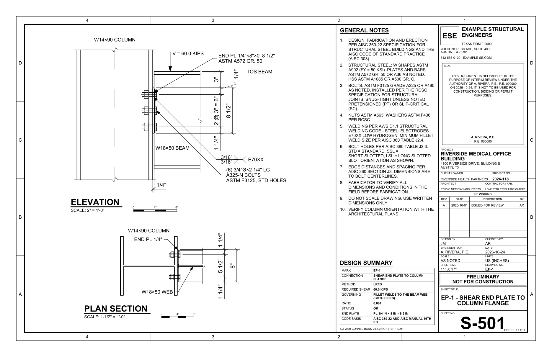
The drawing sheet carries the elevation and the plan. The end-plate detail is on screen and in the report only, because a third view would force every view to a smaller scale. The report has the input table, every check with its calculation and the three views. See Drawings and Reports.
Auto-design for end plates #
Auto-design uses the shared dialog: see Auto-design, compare and batch. For a shear end plate it searches, from the lightest hardware up:
- Bolt diameter: 3/4, 7/8 and 1 in.;
- Rows, n: from 2 up to the number that fits on the web flat (12 at most);
- Thickness: 1/4, 5/16 and 3/8 in. first; 7/16 to 3/4 in. only when the loads include axial tension;
- Fillet to beam web: 3/16 to 3/8 in., the smallest that passes;
- Top of beam to top of plate: moved to the top of the web flat when the current position does not fit;
- Gage: falls back to 5-1/2 in. when the bolts do not fit the support.
Pinned fields are kept. The bolt grade, spacing, edge distances and materials are not searched. The objectives are Lightest (steel weight) (end-plate weight), Fewest bolts and Lowest cost (fabrication estimate) (bolts, welds and plate).
Compare and batch work for this type. The batch columns are mark, beam, support, RD and RL.
Limitations and deviations #
Scope
- Rectangular HSS only. A round HSS support is NOT FEASIBLE.
- Sloped beams, seismic (AISC 341) demands and moments are not modeled. The out-of-plane eccentricity is neglected, as the Manual does for shear end plates. Skewed beams are covered up to 6-15/16 in 12 with fillet welds; see Skewed end plate for what is and is not checked.
- Blind bolts on HSS walls are noted only.
Simplifications
- The girder-web and HSS-wall checks under axial load use approximate yield-line mechanisms, flagged in the results; the Manual gives no equation for these cases.
- With connections on both sides of a web, opposite axial forces are not netted (conservative).
- Prying on a column flange uses the end plate's tributary length (conservative for a continuous flange).
- The slip resistance uses hf = 1.0; the filler thickness does not change it.
- The 3/8-in. flexibility limit becomes advisory when axial tension is present. This is an ILX rule, following Design Example II.A-11B, which uses a 1/2-in. plate.
Verification
- II.A-11A (shear end plate to a girder web), LRFD and ASD: all 19 values match, within 0.6 %.
- II.A-11B (axial tension with prying): 31 of 32 values match, within 0.8 %. The required weld size differs: AISC reads Manual Table 8-4 at 30°, conservatively, and gets 2.08 sixteenths; ILX applies the directional increase at the true angle, 38.7°, and gets 1.96. The 3/16-in. weld is adequate either way.
- II.A-11C (structural integrity): all 12 values match, within 0.9 %.
- Manual Table 10-4: the values printed in the examples match; the other rows are reproduced from the table's stated basis.
See How ILX was verified.