
Designing a seated connection
A seated connection carries the beam reaction on a seat below the bottom flange, with a top angle (or a side angle) for stability. ILX designs unstiffened seats (a seat angle bolted or welded to the support, Manual Tables 10-5 and 10-6) and stiffened seats (a seat plate on a stiffener plate, welded to the support, Manual Table 10-8).
When to use a seated connection #
- Use a seated connection when the beam must be set on the support during erection, for example a beam framing into a column web where a framed connection is hard to erect, or when the connection should sit below the beam.
- Use an unstiffened seat angle for moderate reactions. Use a stiffened seat when the reaction is too large for a seat angle.
- Seated connections carry vertical shear only. For axial force, use a framed connection: a single plate, a double angle or a shear end plate.
- Seats frame to a column flange, a column web or an HSS column wall. They do not frame to a girder web.
Creating one in the wizard #
- In the wizard's Connection type step, select the Seated card in the Simple shear group.
- Under Joint type, select Beam to column flange, Beam to column web or Beam to HSS column. Beam to girder web is not offered. If you come from another type with a girder web, the joint becomes a column flange. On an HSS column a bolted seat angle is bolted to the HSS wall (see Bolted to an HSS wall).
- Under Configuration, select a card:
| Card | Sets | Manual basis |
|---|---|---|
| Bolted seat angle | Seat angle bolted to the support; beam bolted to the seat | Table 10-5 |
| Welded seat angle | Seat angle welded to the support along both vertical edges | Table 10-6 |
| Stiffened seat | Seat plate and stiffener welded to the support | Table 10-8 |
On an HSS column all three cards are available; Bolted seat angle uses through-bolts by default.
- Members. Enter the Connection mark (new marks are numbered SE-1, SE-2 and so on), the Supported beam, the Column or HSS column, and, for a seat angle, the Seat angle.
- Loads. Choose Service D + L (Dead RD, Live RL) or Required strength (Shear Ru or Ra). There is no axial field; the step notes Seated connections carry vertical shear only. The other load modes are in the editor.
- Tick Auto-design the connection (seat, bolts, welds) for these loads to size the connection as it is created. The wizard keeps the beam, the support, the joint type and the configuration (seat type and attachment), and uses the Lightest (steel weight) objective.
- Select Create.
Inputs in the editor #
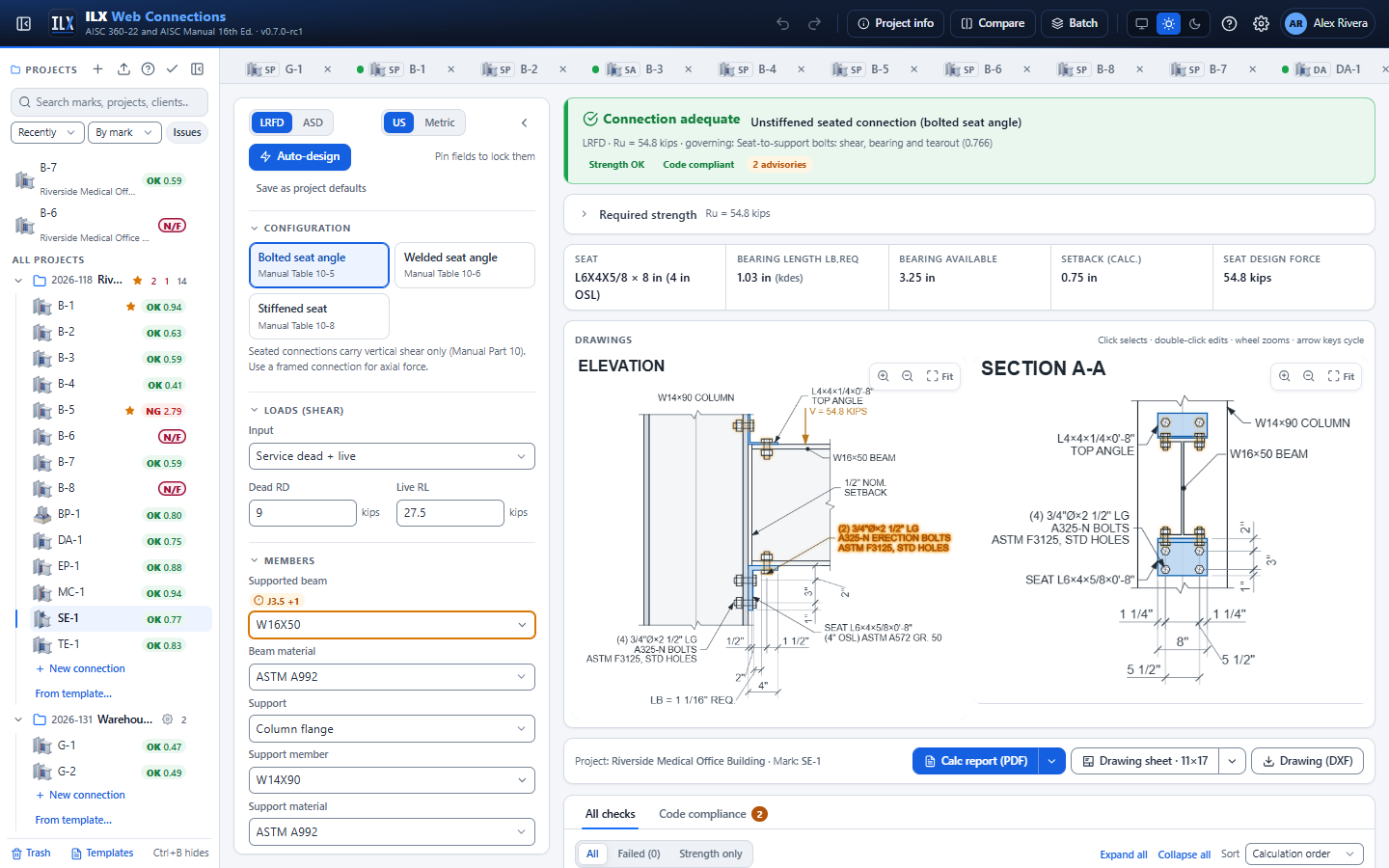
The input panel has these sections, in this order: Configuration, Loads (shear), Members, Seat angle (or Seat plate and stiffener), Bolts, Erection bolts (seat to beam flange), Welds, Stability (top or side angle) and Additional checks. The Welds section shows only for a welded or stiffened seat. Clicking an element on the drawing opens its fields.
The key-geometry strip under the status shows Seat (for example L6X4X5/8 × 8 in (4 in OSL)), Bearing length lb,req with what governs it (yielding, crippling or kdes), Bearing available, Setback (calc.) and Seat design force.
Seat configuration #
| Button | Notes |
|---|---|
| Bolted seat angle (Manual Table 10-5) | Disabled on an HSS wall (Seats are welded to HSS walls) |
| Welded seat angle (Manual Table 10-6) | |
| Stiffened seat (Manual Table 10-8) | Always welded |
The section notes that seated connections carry vertical shear only, and that a framed connection should be used for axial force.
Loads (shear only) #
The Loads (shear) section works as described in Loads and load combinations, without the axial fields. All four Input modes are offered: Service dead + live (Dead RD, Live RL), Service components → ASCE 7 combinations (RD, RL, RLr, RS, RW, RE), Required strength Ru (Ra in ASD) and Factored load cases (table) (a name and V per case). With several combinations, each check is enveloped and the Combo column shows the governing one; shear is taken as |V|.
If a file contains axial input (PD, PL or P), a note says it is not used. The check Axial force: not applicable to seated connections (shear only) then fails, and no strength check uses the axial force.
Members and support #
| Field | Options and notes |
|---|---|
| Supported beam, Beam material | A W, M, S or HP shape |
| Support | Column flange, Column web or HSS column wall |
| Support member, Support material | A W shape, or an HSS for an HSS wall. HSS materials are limited to A500, A1085 and A53 Gr. B. |
| Connected HSS face | HSS wall only: B (wide face) or H (narrow face) |
| Bolts into the HSS, Blind bolt available strength per fastener (manufacturer) | Bolted seat on an HSS wall only: through-bolts (default) or blind bolts with the manufacturer's value (default 0); see Bolted to an HSS wall |
| Seats on both sides of the web (same level) | Column web only. The support thickness is shared by the two seats (bolt bearing, and base metal by Manual Eq. 9-7, 6.19 D/Fu). For a stiffened seat it replaces the web yield-line check. |
| Setback (nominal), Beam length underrun | Default 1/2 in. and 1/4 in. The calculations use setback + underrun (3/4 in., Manual Part 10). |
| Beam offset from support centerline | Beam centerline off the column centerline (Design Example II.A-16) |
Switching Support to HSS column wall changes a W-shape member to an HSS12X12X1/2 in A500 Gr. C (rectangular); a bolted seat angle stays bolted (to a round HSS it becomes welded). Switching back from an HSS changes the member to a W14X90 in A992.
Seat angle, or seat plate and stiffener #
For a seat angle (Seat angle section):
| Field | Options and notes |
|---|---|
| Seat angle | An AISC L shape (default L6X4X5/8) |
| Angle material | A572 Gr. 50 (default), A36 and so on |
| Outstanding leg (under the beam) | Short leg or Long leg. The outstanding leg (OSL) sets the bearing length available. |
| Angle length | Along the support face (default 8 in.) |
| Design bearing length (0 = lb,req) | The lb used for the outstanding-leg flexure. The Manual tables are entered with lb rounded up (for example 1-1/8 in.); 0 uses the computed lb,req. |
| Seat shift from beam centerline | Moves the seat along the support face |
For a stiffened seat (Seat plate and stiffener section):
| Field | Options and notes |
|---|---|
| Seat width W (projection) | The projection from the support face |
| Stiffener length l | The vertical length of the stiffener and its welds |
| Stiffener thickness, Plate material | 3/8 in. to 1 in.; the material applies to the seat plate and the stiffener |
| Seat plate thickness, Seat plate width (along the support) | 3/8 in. to 3/4 in.; width B |
| Stiffener corner clip | Reduces the fitted bearing area under the seat plate |
| Seat shift from beam centerline | As for the seat angle |
Beam bearing stiffeners (J10.8) is a section of its own, below the seat:
| Field | Options and notes |
|---|---|
| Beam bearing stiffeners over the seat | None (default; saved connections are unchanged), Design when required or Provided (as entered) |
| Stiffener thickness | Provided only; otherwise designed (the next standard plate) |
| Stiffener width (0 = max) | 0 uses the largest 1/8 in. that fits (bf − tw)/2 |
| Stiffener length | Full depth (default) or Half depth (from the bottom flange) |
| Corner clip (min.), Stiffener fillets (min.), Stiffener material | Clips and fillets are increased as needed with Design when required |
| Finished to bear on the bottom flange (J7) | On by default: fitted bearing on the loaded flange, checked with Eq. J7-1 |
Bolts and holes #
Bolt grade, Bolt diameter and Threads apply to every bolt: the seat bolts, the erection bolts and the top angle bolts. For a bolted seat angle the section also shows:
| Field | Options and notes |
|---|---|
| Joint | Bearing (snug / pretensioned) or Slip-critical; Surface Class A (μ = 0.30) or Class B (μ = 0.50) |
| Rows, Columns | 1 to 4 each, under Seat to support |
| Heel to first row, g1, Row pitch, Column gage | Rows go down the vertical leg from the heel; columns go across |
| Holes in angle, Holes in support | STD, OVS, SSL horizontal, SSL vertical, LSL horizontal, LSL vertical |
| Hole deformation at service is a design consideration (2.4 / 1.2) | Ticked: bearing 2.4 d t Fu and tearout 1.2 lc t Fu. Cleared: 3.0 and 1.5. |
Erection bolts #
The Erection bolts (seat to beam flange) section places the bolts through the seat and the beam bottom flange. They hold the beam in place and carry no design load.
| Field | Options and notes |
|---|---|
| Number of erection bolts | 0 to 4 (2 required by Manual Part 10) |
| Holes | STD, OVS, SSL across the beam or SSL along the beam |
| Gage across the flange, Support face to bolt line | The bolt gage and the distance x from the support face |
Seat welds #
| Field | Shows for | Notes |
|---|---|---|
| Fillet, each vertical edge | Welded seat angle | One fillet along each vertical edge of the vertical leg |
| 2w returns at the top | Welded seat angle | The returns of Manual Table 10-6 |
| Stiffener + seat plate to support (both sides) | Stiffened seat | Both faces of the stiffener, and the seat plate to the support |
| Seat plate weld length each side (0 = 0.2 l) | Stiffened seat | Seat plate to support, each side of the stiffener (Manual Fig. 10-11b) |
| Seat plate to stiffener (both sides) | Stiffened seat | Same length as the seat-plate-to-support weld |
| Electrode | Welded and stiffened seats | E70XX or E80XX |
Top or side angle #
| Field | Options and notes |
|---|---|
| Stability | Top angle (top flange), Side angle (top of web) or None. None fails a code-compliance check. |
| Angle, Material, Angle length | Default L4X4X1/4 in A36, 8 in. long |
| To the support | Top angle only: Bolted (2 bolts) or Welded along the toe only, with the Toe weld size |
| Gage, heel to bolt line, Bolt spacing | The bolt line in each leg and the spacing of the two bolts. The beam leg is always bolted. |
Additional checks #
Tick Structural integrity tension (AISC 360 B3.9) to add the integrity checks as an independent case. See Structural integrity.
Tick Cyclic loading (fatigue, AISC 360 Appendix 3) to design the seat for fatigue, with the cycle count and the cyclic range of the reaction as for the single plate; see Fatigue (Appendix 3). The details: the seat outstanding leg in bending at the critical section (rolled base metal, Table A-3.1 Case 1.1, A), the vertical leg at the bolt holes (Section 2, or Case 1.5 for snug-tight joints), the seat-to-support welds (two lines of the vertical-leg length with the reaction at setback + lb/2, elastic, Case 8.2, F) and, for a stiffened seat, the stiffener-to-support welds (the reaction at 0.8 W, Case 8.2, F).
The checks it runs #
Each check cites the clause shown below. See Checks and compliance for reading the results.
Beam web at the seat #
- Required bearing length lb,req = max(lb,yielding, lb,crippling, kdes) (Manual Eqs. 10-1 to 10-3, Table 9-4 constants R1 to R6). For a seat angle, lb,req must fit on the OSL minus setback and underrun; for a stiffened seat, W ≥ lb,req + setback + underrun.
- Beam web local yielding at the seat (J10.2, Eq. J10-3) and Beam web local crippling at the seat (J10.3, Eq. J10-5a or J10-5b), at the bearing length available.
- Beam web shear (end of beam) (G2.1).
- With an offset beam (II.A-16), the seat elements are designed for twice the more highly loaded weld line or bolt column, shown as Seat design force.
Beam bearing stiffeners over the seat #
With Beam bearing stiffeners set to Design when required, ILX adds a stiffener pair over the seat when the beam web fails local yielding or crippling, or the required bearing length does not fit (with Provided, always). The pair stands mid-way along the bearing available on the seat and carries the whole reaction (the rule ILX uses for every bearing stiffener):
- Bearing stiffeners, over the seat: full load (J10.8, J4.4): two stiffeners plus a 12tw web strip (the beam end) as a column, Lc = 0.75h; Lc/r ≤ 25 gives Pn = Fy Ag (Eq. J4-6), otherwise Chapter E.
- J10.8 detailing: width + tw/2 ≥ b/3 of the seat, thickness ≥ half the seat thickness and ≥ width/16, length ≥ ½ depth (¾ when crippling governs); corner clips that clear the beam fillets.
- Fitted bearing stiffeners on the loaded flange (J7), 1.8 Fy Apb with Apb net of the clips (or fillet welds to the flange when not fitted); fillet welds to the web; beam web shear rupture along those welds (J4.2); minimum fillet size.
- Bearing stiffeners stand over the seat bearing and, as a recommendation, clear the erection bolt nuts on the bottom flange.
When the stiffeners are adequate, Beam web local yielding / crippling at the seat become recommendations titled bearing stiffeners required, the bearing-length fit (lb,req, or W ≥ lb,req + setback for a stiffened seat) becomes a recommendation as long as the bearing available is at least kdes, and the seat flexure takes the reaction at the stiffeners (e = setback + underrun + lb,available/2 − (t + 3/8 in.)). The drawings show the pair edge-on in the elevation and face-on with its corner clips in Section A-A.
The column under the seat has no J10 check: the seat reaction runs along the column, not normal to its flange (J10 covers forces normal to the flange). On a column web, the Ellifritt and Sputo yield line above is the support check.
Outstanding leg of the seat angle #
- Seat angle outstanding leg: shear yielding, 0.60 Fy L t (J4.2).
- Seat angle outstanding leg: flexural yielding (F11), Mn = Fy L t²/4 at the critical section t + 3/8 in. from the back of the vertical leg, with the reaction at mid-bearing.
- Recommendations: thickness 3/8 in. to 1 in. (the range of Tables 10-5 and 10-6), and seat length ≥ beam flange width.
Seat-to-support bolts #
- Seat-to-support bolts: shear, bearing and tearout (J3.11): the sum of the least of shear, bearing and tearout of each bolt. The angle tears out toward the bolt above, the support toward the bolt below. The eccentricity of the bolt group is neglected, as in Table 10-5. The calculation also shows the Table 10-5 tmin for bolt shear to govern.
- Seat-to-support bolts: slip resistance (J3.9), for slip-critical joints.
- Seat angle vertical leg: shear rupture through the top bolt row (J4.2). This is not a Table 10-5 limit state; ILX checks it for completeness.
- Detailing: row pitch and gage (J3.4), edge distances below the bottom row, to the angle ends and in the column flange (J3.5), maximum edge distance (J3.6), tightening clearances to the outstanding leg, the column web or the column flanges (Manual Part 7), hole types that need slip-critical bolts (J3.3), long slots in one ply only, pretensionable bolts and Group C sizes (J3.2).
Seat-to-support welds #
- Seat angle to support welds (J2.4, Manual Table 10-6 elastic method): two vertical welds over the vertical leg length, with the reaction at mid-bearing.
- Base metal: Support thickness ≥ tmin to develop the seat welds (Manual Eqs. 9-6 and 9-7). When the support is thinner, the weld strength is reduced by t / tmin.
- Weld size: minimum (Table J2.4) and maximum t − 1/16 in. along the angle edge, length ≥ 4w (J2.2b), and the 2w returns.
Stiffened seat #
- Stiffener and seat plate to support welds (J2.4, Manual Table 10-8, e = 0.8 W): two welds l plus 0.2 l under the seat plate each side. Base metal and weld reduction as for the welded seat.
- Seat-plate welds ≥ 0.2 l each side, and no longer than the seat-plate overhang (B − ts)/2. The seat-plate-to-stiffener weld must be at least the size of the seat-plate-to-support weld.
- Stiffener thickness: to develop the seat-plate welds (1.5w for Fy = 50 ksi, 2w for Fy = 36 ksi with E70), and ≥ (Fy,beam / Fy,stiffener) tw.
- Stiffener width-to-thickness W/ts ≤ 0.56 sqrt(E/Fy) (B4.1), local buckling.
- Stiffener bearing under the seat plate (fitted) (J7, Eq. J7-1), 1.8 Fy (W − clip) ts.
- Recommendations: seat plate ≥ 3/8 in.; stiffener finished to bear.
Column web and HSS wall #
- Column web yield line under the stiffened seat (Ellifritt & Sputo): stiffened seats on a column web, Ellifritt and Sputo (1999) Eq. 2 with the 2000 errata, φ = 0.90 / Ω = 1.67. With seats on both sides of the web at the same level, it is replaced by a note.
- Stiffened seat on an HSS wall: HSS face width ≥ max(0.4 l, 2 × seat weld) + ts + 2 (2.25 t) (Design Example K.5), and the HSS wall strength factor Ru W / t² against Manual Table 10-15. The table covers square and rectangular HSS with Fy = 50 ksi and Fu = 62 ksi (ASTM A500 Grade C; its header), widths B = 5, 5.5, 6, 7, 8, 9, 10, 12, 14, 16, 18 and 20 in., and stiffener lengths l = 6 to 32 in. Inside it, ILX reads the table (LRFD or ASD column) and checks the required factor against it. A length between whole inches uses the next lower tabulated l: the Manual warns against interpolating. A "–" entry fails as a detailing check, because the Manual says the HSS flat is then too narrow for a 0.2l weld on each side of the stiffener. Outside the table (another width, length or material, e.g. A1085 with Fu = 65 ksi), ILX reports the required factor as a recommendation and says the table does not cover the case.
- Seats on an HSS wall must sit on the flat of the wall (B − 3t); on a round HSS, within half the diameter.
Erection bolts and stability angle #
- Two erection bolts connect the beam flange to the seat; gage ≥ 2⅔d (J3.4); edge distances to the seat toe, the beam end (with underrun), the seat ends and the beam flange tips (J3.5; the flange tip is advisory); tightening clearance to the seat vertical leg or the stiffener.
- Top or side angle: a stability angle is required (Manual Part 10); thickness ≥ 1/4 in.; thicker than 1/4 in. not recommended (Manual 16th Ed.) and legs ≥ 4 in. (advisory); toe weld size limits (J2.2b); bolt edge distances, gage and tightening clearance.
Structural integrity (B3.9) #
With Structural integrity tension ticked, ILX checks the nominal tension T = (2/3) Vu (LRFD) or Va (ASD), at least 10 kips (B3.9(b), Design Example II.A-12B), against:
- erection bolt shear, bearing 3.0 d t Fu and tearout 1.5 lc t Fu on the seat;
- block shear of the beam bottom flange;
- bolted seat: seat bolt tension (top row) and seat angle bending with prying (Manual Part 9);
- welded seats: the welds in tension (approximate).
It also reports the column bracing capacity, B3.9(c).
Geometry feasibility #
The connection is NOT FEASIBLE (see NOT FEASIBLE) when, for example, the seat gives no bearing beyond the beam end, the OSL is shorter than lb,req + setback + underrun, the seat does not fit the column flange, the web between the fillets (T) or the HSS flat, seat bolts are off the vertical leg or in a web fillet, erection bolts miss the beam flange or the seat, the top angle is longer than the web T, or a side angle is deeper than the beam web clear depth.
Bolted to an HSS wall #
With Support = HSS column wall and a Bolted seat angle, the seat-to-support bolts go into the wall of a rectangular HSS. This is the less common case: with HSS columns the connecting element is typically shop-welded to the HSS and bolted to the beam (Manual 16th Ed. p. 10-96), and Manual Table 10-5 does not cover HSS supports.
Inputs (Members section, shown only for a bolted seat on an HSS wall)
| Field | Default | Notes |
|---|---|---|
| Bolts into the HSS | Through-bolts | Through-bolts (snug-tight, J3.11b): long bolts through the whole tube, both walls (Manual p. 7-12). Blind bolts (manufacturer, J3.12): special fasteners installed from one side (Manual p. 7-13). |
| Blind bolt available strength per fastener (manufacturer) | 0 | Blind bolts only: the manufacturer's available shear strength per fastener in the design method you use (φRn for LRFD, Rn/Ω for ASD), in kips or kN. 0 fails the design until you enter it. |
Checks
- Through-bolts: each seat bolt takes the least of the bolt shear (Table J3.2, single shear at the seat/HSS interface), the seat angle bearing and tearout (J3.11a), and the HSS wall bearing and tearout of Spec J3.11b: bearing Rn = 1.8 Fy d t (J7, Eq. J7-1, φ = 0.75, Ω = 2.00) and tearout 1.2 lc t Fu (Eq. J3-6g; 1.5 lc t Fu, Eq. J3-6h, when deformation is not a design consideration; 1.0 lc t Fu, Eq. J3-6i, for long slots perpendicular to the force). t is the HSS design wall thickness, Fy and Fu those of the HSS material; the wall tears out only toward the bolt below (the column is continuous).
- Through-bolts are snug-tight only: the flexibility of the HSS walls precludes pretensioning (Manual p. 7-12). A Slip-critical joint fails.
- The bolt grip is the seat angle leg plus the whole HSS depth across the connected face. Long bolts may need ASTM A449 (Manual p. 7-12); the threads-excluded check uses this grip.
- Blind bolts: each bolt takes the least of your manufacturer value, the HSS wall bearing and tearout (J3.11a with the design wall thickness) and the seat angle bearing and tearout, with the bolt value labelled as manufacturer's data (J3.12).
- Both kinds: every hole must lie on the flat of the connected HSS face, or the hole check fails (NG). The whole seat angle must also sit on the flat (NOT FEASIBLE otherwise). Seated connections carry no axial force, so the J3.13 bolt-tension case does not arise.
Gaps. The HSS-wall limit states of a blind bolt (tear-out of the bolt in tension, wall distortion) are the manufacturer's: confirm them with the product literature. There is no HSS wall plastification check under the seat (as for the welded seat, Design Example K.4). Through-bolts pass through both walls: coordinate them with any connection on the opposite face. Round HSS is not available. The top angle bolts are detailing only, as on other supports.
The drawing shows through-bolts crossing the tube with the nut on the far wall, and the seat bolt callout adds THROUGH-BOLTS, SNUG-TIGHT (AISC 360 J3.11b) or BLIND BOLTS PER MANUFACTURER (AISC 360 J3.12).
Drawings, report and sheet #
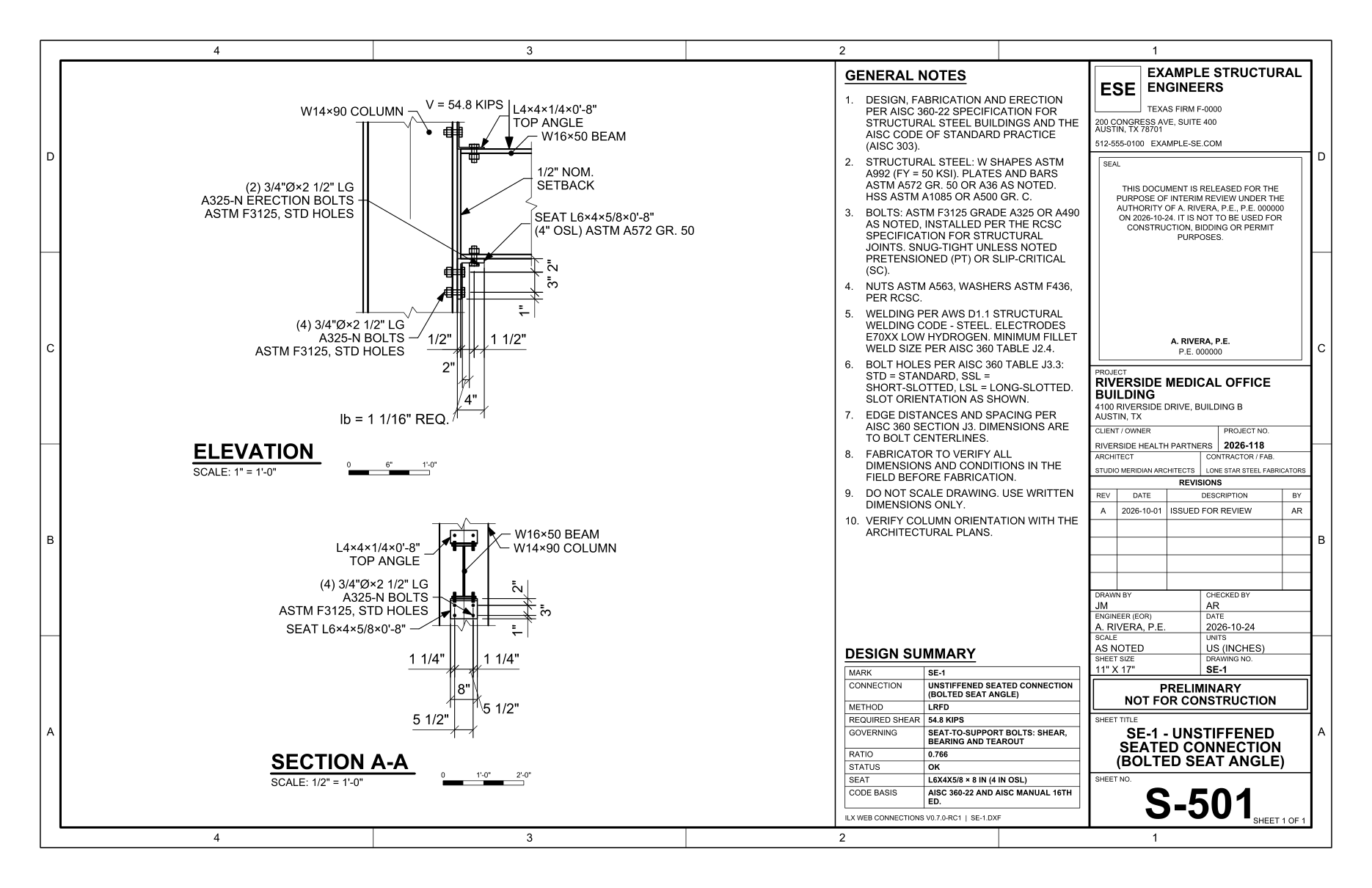
ILX draws two views:
- ELEVATION: the support profile, the beam end at the nominal setback, the seat angle (or seat plate and stiffener), the top or side angle, every bolt and weld, the setback, bearing-length and bolt dimensions, and the AWS weld symbols.
- SECTION A-A: looking at the support face, with the beam cross-section, the seat with its bolt pattern or edge welds (with returns), the stiffener, the top angle, the support edges and fillet lines, the bolt gages and the offset from the support centerline.
The weld symbols follow the calculation: one fillet on each vertical edge of a seat angle (with the return length in the tail, or NO RET.), both sides of the stiffener, the seat plate to the support EA. SIDE, and a field weld along the toe of a welded top angle. Bolt callouts give each group's bolt length.
The drawing sheet carries both views, the general notes and the design summary, with the seat description in the SEAT row. The report is titled Seated Beam Connection, and its input summary states that axial force is not applicable. See Drawings and Reports.
Auto-design, compare and batch #
Auto-design uses the shared dialog; see Auto-design, compare and batch. It never changes the seat type or attachment. It searches:
- Seat angle (bolted or welded): seat angles from L4X4X3/8 to L8X4X1, lightest first, with the short or long leg out and lengths of 6 or 8 in. A bolted seat also searches 1 to 3 bolt rows and, unless pinned, 3/4, 7/8 and 1 in. bolts, with g1 set for the tightening clearance. A welded seat searches fillets from 1/4 to 1/2 in., up to t − 1/16 in.
- Stiffened seat: W from 5 to 9 in., l from 9 to 24 in. and fillets from 1/4 to 7/16 in. (the same size seat plate to stiffener). The stiffener thickness is set from the weld, the W/ts limit and the beam web.
Pinned fields are kept. The objectives are Lightest (steel weight), Fewest bolts (seat and erection bolts) and Lowest cost (fabrication estimate).
Compare works as for the other types. Batch starts with the columns beam, support, RD and RL.
Limitations and documented deviations #
- Shear only. Axial input is reported as not applicable and never used.
- No girder supports. Bolted seats on a rectangular HSS wall use through-bolts or blind bolts; see Bolted to an HSS wall.
- Bolted stiffened seats (two angles as the stiffener, Manual Table 10-7) are not available.
- Manual Table 10-15 (stiffened seats to HSS) is looked up only where it applies (Fy = 50 ksi and Fu = 62 ksi, tabulated widths and lengths). K.5 (HSS14, l = 24 in.) reads 4,250 / 2,830 kip/in. against the required 3,880 / 2,590 kip/in. Outside the table, ILX reports only the required factor.
- Unstiffened seats on HSS walls are checked for base metal only, as in Design Example K.4. There is no wall plastification check. On a round HSS, the seat is kept within half the diameter as a flat-face proxy.
- Column web yield line. The φ = 0.90 / Ω = 1.67 applied to Ellifritt and Sputo's nominal strength is an engineering choice. Unstiffened seats on a column web have no yield-line check.
- Seat bolt group. Eccentricity is neglected (Table 10-5 practice). Unequal bolt-column forces are taken into account only for offset seats, as twice the larger force.
- Integrity of welded seats uses the weld throat in tension. Flexure of the seat leg and the support under the integrity tension is not evaluated.
- Top angle and erection bolts are detailing only; they are not designed for load, as in the Manual.
- Design Example II.A-12A bolt shear. The Example quotes 107 / 71.6 kips for four bolts. ILX gives 71.6 / 47.7 kips (4 × 17.9 and 4 × 11.9 kips); the quoted figures are six-bolt values. The conclusion is unchanged.
- Verification. ILX reproduces Design Examples II.A-12A, II.A-12B, II.A-13, II.A-14, II.A-15, II.A-16, K.4 and K.5 in LRFD and ASD, and Ellifritt and Sputo's Examples 1, 3 and 4. The checked values agree within 0.5 % (for example the 113-kip OSL strength as 112.5 kips, the 139-kip Table 10-8 weld as 139.4 kips), and every published conclusion is reproduced. See Verification.