
Designing a truss connection
What the truss connection covers #
The truss connection type designs the two joints of AISC Design Examples v16.0, Chapter IIC, for AISC 360-22 and the AISC Manual, 16th Ed. (Parts 7, 8, 9 and 13):
| Joint | Example | What it is |
|---|---|---|
| Support joint | II.C-1 | A WT top chord framing into a column flange. A gusset plate is welded (CJP) to the chord stem, the double-angle diagonal is fillet-welded to the gusset, and two clip angles are welded to the gusset and bolted to the column flange. |
| Panel point | II.C-2 (joints L1 and U1) | Double-angle (or single-angle) web members fillet-welded at heel and toe directly to the WT chord stem, optionally on a stem extension plate CJP-welded to the stem. |
The editor designs the joint live, like every other type. Every change re-runs the full design and updates the status, the drawings and the checks.
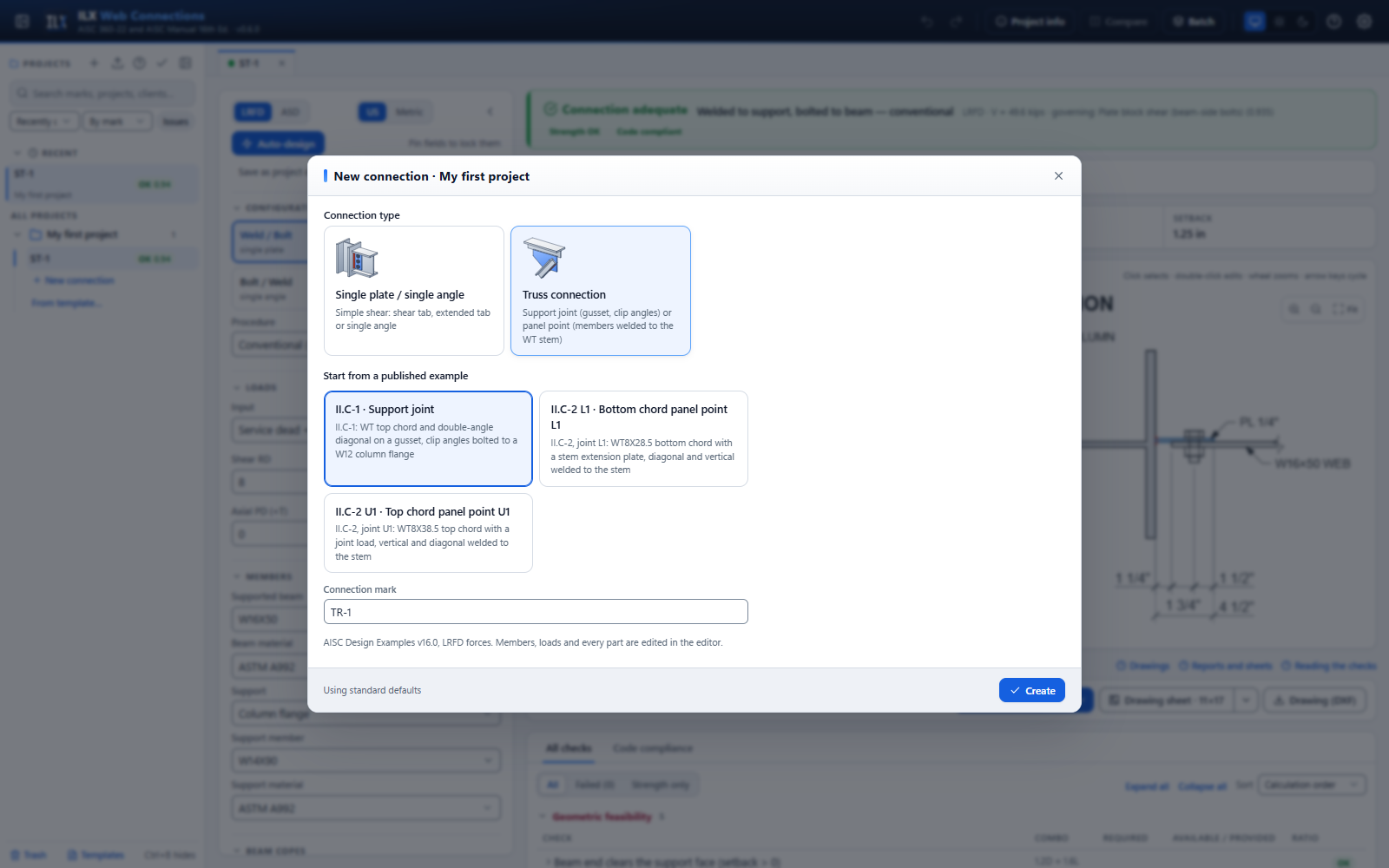
- Create it. In the file manager, click New connection, choose Truss connection, pick one of the published examples to start from, and click Create. New marks are numbered TR-1, TR-2 and so on.
- Pick the joint. Choose Support joint or Panel point. The example buttons (II.C-1, II.C-2 L1, II.C-2 U1) reload a published joint at any time.
- Enter the loads, the chord and the web members, then the parts of the joint.
- Read the status bar and fix what fails (see Checks and compliance).
- Produce the outputs: the calculation report and the drawing sheet (PDF and DXF).
The joint and the working point #
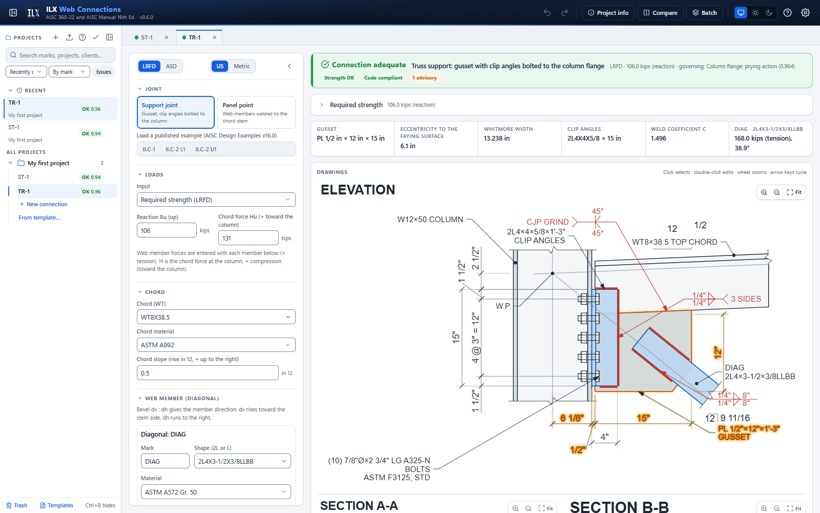
All geometry is measured from the working point (W.P.). At a panel point the W.P. lies on the chord work line, which is the centroid line of the WT. At a support joint it lies on the column centerline (II.C-1) or, if you choose, on the column face.
- W.P. at the column centerline. The reaction is eccentric to the bolts on the column flange by the column half-depth, e = d/2. The bolts then take tension as well as shear (see Bolts).
- W.P. at the column face. e = 0 and the bolts take shear only. Move the diagonal end out by the same amount so the welds stay on the gusset.
The column moment from the support eccentricity is reported as a note (see Manual Part 13 truss items).
Loads at a truss joint #
| Field | Meaning |
|---|---|
| Input | Required strength: forces entered directly as Pu (LRFD) or Pa (ASD). Service D + L: dead and live components, combined as max(1.2D + 1.6L, 1.4D) for LRFD or D + L for ASD. |
| Reaction R (support joint) | Truss end reaction, upward. |
| Chord force H (support joint) | Axial force in the top chord at the column, + compression toward the column. If H is tension, the bolts also take it (equally per bolt). |
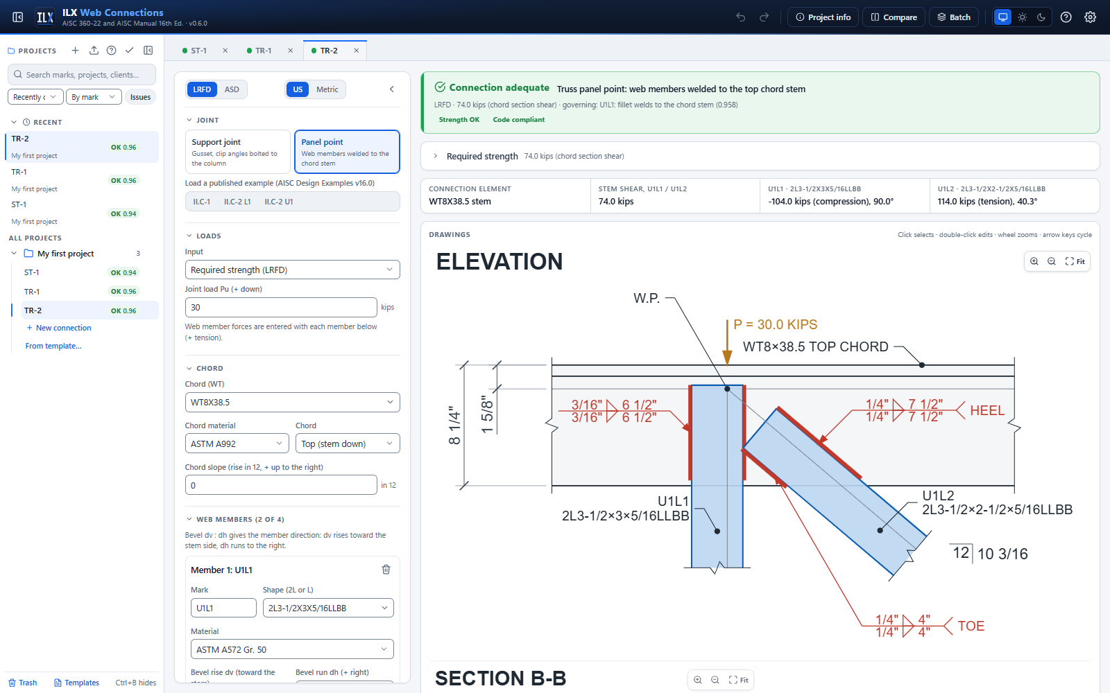
| Joint load (panel point) | Load applied at the W.P., + downward (II.C-2 joint U1: 30 kips LRFD, 20 kips ASD). |
| Member force P | In each web member, + tension, − compression. |
ILX checks equilibrium of the joint as an advisory. A support joint is checked with the diagonal, the reaction and the chord force. A panel point is checked perpendicular to the chord; the difference in chord force carries the rest. An unbalance above 5 % is flagged so you can catch a sign or a typing error.
The chord #
- Chord (WT): any WT from the AISC Shapes Database v16.0, with its material.
- Chord position: Top (stem down) or Bottom (stem up). A support joint uses a top chord.
- Chord slope: rise in 12, + rising to the right (II.C-1: ½ in 12). The chord, its flange, stem and k-line are drawn on the slope.
Welds and member legs must stay on the stem below the k-line. A member that runs into the chord flange makes the joint NOT FEASIBLE. One that only reaches into the flange-to-stem fillet (the k-area) is flagged under Code compliance.
Truss web members #
Each web member is a double angle (2L…LLBB, 2L…SLBB or an equal-leg 2L) or a single angle (L…, choosing which leg lies on the plate). A support joint uses one member, the diagonal. A panel point takes up to four.
| Field | Meaning |
|---|---|
| Bevel rise dv : run dh | The member direction, as on the drawings. dv rises toward the stem side (into the truss); dh runs to the right (negative to the left). A vertical is 1 : 0. |
| W.P. to member end | Distance along the work line from the W.P. to the end of the angles. Negative values are allowed: the member then starts behind the W.P. |
| Heel to work line | Gage from the heel to the work line. Leave it blank to use the centroid (II.C-1 uses the detailed 1¼ in.). |
| Heel side | Which side of the member the heel is on, looking along the member away from the W.P. |
| Weld size, heel and toe lengths | Fillet welds along the heel and the toe of each angle, starting at the member end. Unequal lengths are allowed (II.C-2 U1L2: 7½ in. heel, 4 in. toe). |
What is checked for each member:
- Weld strength: φRn = n × 0.60 FEXX × 0.707 w × (l_heel + l_toe), with kds = 1.0 for load along the weld and β for welds longer than 100w (J2.2b(d)).
- The calculation also prints the required length per angle and per weld line, as the examples do.
- Balancing the welds about the member's centroid is not required for statically loaded angle members (J1.7).
- Weld size limits: minimum from Table J2.4 (thinner part joined), maximum t − 1/16 in. along the angle edges, and minimum length 4w.
- Base metal: angle tmin = 3.09 D/Fu (Manual Eq. 9-6). Gusset or chord stem tmin = 6.19 D/Fu (Eq. 9-7), because the angles on both faces share the plate.
- Tension members:
- yielding, Fy Ag;
- rupture, Fu U Ag, with U from Table D3.1 Case 4: U = 3l²/(3l² + w²)(1 − x̄/l), where l is the average weld length and w the connected leg;
- block shear of the gusset or stem around the welds.
- Compression members: the member's own buckling belongs to the truss design. At a support joint the gusset is checked as a column strip on the Whitmore section (see below).
Support joint: column #
Choose the column (W shape) and its material. The clip angles are bolted to its flange. ILX checks the following:
- Prying. Prying on the column flange, with the same Manual Part 9 procedure as the angles, using tf, b = (g − tw)/2 and p = s.
- Bearing and tearout. Bearing and tearout on the flange between holes.
- Bolt fit. The bolts must fit on the flange, and the holes must clear the web-to-flange fillet (g/2 − dh/2 ≥ k1).
Support joint: gusset plate #
| Field | Meaning |
|---|---|
| Gusset thickness, material | II.C-1: PL ½ in., A572 Gr. 50. A recommendation flags a gusset thinner than the chord stem. |
| Width | Along the chord, from the setback edge (II.C-1: 1'-3"). |
| Depth below the stem | Measured at the column edge (II.C-1: 12 in.). |
| Setback | Column face to the gusset and the chord end (½ in.). |
| Edge beyond the welds | The corner below the diagonal is cut square to the diagonal, this far past the end of its welds. |
| Whitmore width | Full (Manual Fig. 9-1, as the example) or Clipped (only the part within the gusset and the CJP-welded chord stem). |
| Gusset buckling K and length | DG29 Table C-1 (default) or Given K with the average length. With the DG29 setting the support gusset is a corner gusset (see below). |
| K (compression) | Shown for Given K only: the effective length factor with the Thornton average length (0.5, the earlier ILX default). |
Gusset checks:
- Whitmore section.
- lw = w + 2 l tan 30°, and Aw = lw t.
- Tension: yielding, Fy Aw.
- Compression (AISC Design Guide 29, App. C, Table C-1, after Dowswell 2006): the support gusset is a corner gusset. ILX measures c, the distance from the end of the diagonal's welds to the edge that the centre line meets (DG29 Fig. C-4). If t ≥ tβ = 1.5 √(Fy c³ / (E l1)) the gusset is compact and only yielding applies, Fy Aw. Otherwise it is checked as a column with K = 1.0 and the average L̄ of three lines from the Whitmore section back to the gusset edge (Thornton). J4.4: Fy Aw when KL/r ≤ 25; Chapter E otherwise. With Given K, K × L̄ is used as before.
- Whitmore section within the plate (advisory). It reports how much of lw lies inside the gusset and stem. In II.C-1 only part of the 13.2 in. width lies inside the published gusset outline. The example, like Manual Fig. 9-1, uses the full width, so ILX does too by default. Choose Clipped for the conservative check.
- Shear yielding and rupture of the vertical section through the gusset and the stem at the clip-angle toe.
- Gusset-to-stem CJP.
- Interface forces, as in Design Example II.C-1:
- compression between the WT and the column, C = n′ rut;
- horizontal shear H = Hchord − C;
- vertical tension V = R n′/n;
- moment about the column face, M = C (w.p. to the top bolt) + H (d − ȳ) − V (width/2 + setback).
- The gusset base metal at the CJP is then checked for the normal stress V/(tL) + 6M/(tL²) and the shear stress H/(tL).
- Interface forces, as in Design Example II.C-1:
- Feasibility.
- The diagonal's welds must lie on the gusset or stem.
- The diagonal must clear the clip angles and the chord flange.
- The chamfer must leave a usable gusset.
Support joint: clip angles #
Two angles (II.C-1: 2L4×4×⅝ × 1'-3"), one on each face of the gusset, with one leg welded to the gusset and stem and the other bolted to the column flange.
| Field | Meaning |
|---|---|
| Clip angles | The angle size (one angle, or the 2L designation), with its material. |
| Leg on the column | For unequal legs: which leg is bolted to the column. |
| Length | Angle length (II.C-1: 15 in.). |
| W.P. to top of the angles | Vertical distance from the horizontal line through the W.P. (II.C-1: 2½ in.). |
Checks:
- Shear yielding and rupture. Shear yielding 0.60 Fy Agv (Agv = 2 l t), and shear rupture 0.60 Fu Anv with the holes at dh + 1/16 in. (B4.3b).
- Block shear. Shear along the bolt line from the bottom edge, and tension from the bolts to the angle toe.
- Prying (Manual Part 9, 16th Ed. with Fu):
- a is the lesser of (bf − g)/2 on the column flange and the bolt-to-toe distance on the angle;
- b = (g − tg − t)/2;
- p = l/n, but not more than s;
- then δ, tc, α′ and Q, and the available tension per bolt Q Tc ≥ rut.
- Feasibility. The angles must fit between the chord flange (clear of the k-area) and the bottom of the gusset.
Support joint: bolts #
Bolt grade, diameter, threads (N or X), hole types in the angles and the column, bearing-type or slip-critical joint (Class A or B), and hole deformation at service (bearing 2.4 / tearout 1.2, or 3.0 / 1.5). The pattern has n rows of two bolts (one per angle) at spacing s, a top edge distance lev and a gage g across the column flange.
- Shear, bearing and tearout.
- The group strength is the sum of each bolt's least strength (J3.7 Commentary, as II.C-1).
- Each bolt takes the least of: bolt shear (with the long-joint factor above 38 in.); bearing and tearout of the angle, where the top bolt's lc = lev − dh/2 and the interior bolts' lc = s − dh; and bearing and tearout of the column flange.
- Tension with shear (Manual Part 7, Case II).
- The neutral axis is at the bolt-group centroid.
- rut = R e/(n′ dm), where n′ is the number of bolts above the neutral axis and dm is the moment arm between the tension and compression resultants (II.C-1: 4 bolts, 9.00 in.).
- The tension is combined with the shear stress frv by J3.8: F′nt = 1.3 Fnt − (Fnt/φFnv) frv ≤ Fnt.
- Slip-critical joints. μ Du hf Tb ns ksc, with ksc reduced for the bolt tension (J3.9).
- Detailing.
- Spacing: at least 2⅔d, preferably 3d, and at most 24t or 12 in.
- Edge distances (Table J3.4) to the angle ends, to the angle toe and to the column flange tip; maximum edge distance.
- Tightening clearance from the gusset face (Manual Tables 7-15/7-16).
- The column fillet.
- Slip-critical bolts are required for oversized or slotted holes parallel to the load.
Support joint: clip-angle weld #
A fillet weld on each angle, C-shaped. It runs along the toe of the angle leg on the gusset (the full angle length), with returns along the top and bottom of the leg. With a sloped chord the two returns differ (II.C-1: 3⅜ in. and 2¾ in.).
- Average the returns (default, as the example): kl = (top + bottom)/2. Turn it off to solve the true unequal shape.
- Strength.
- ILX solves the weld group by the instantaneous-center method (Manual Part 8, the geometry of Table 8-8, angle 0°).
- The load is the reaction R/2 per angle, at al = e + (leg on the gusset) − xl from the weld centroid.
- It reports C, k = kl/l, xl, a = al/l, the minimum weld size Dmin and the capacity 2 C C1 D l.
- Limits.
- Minimum and maximum fillet sizes.
- The gusset must be thick enough to develop the welds on both faces (6.19 D/Fu).
- The returns must fit on the part of the angle leg over the gusset; if they don't, the joint is NOT FEASIBLE.
Panel point: stem extension plate #
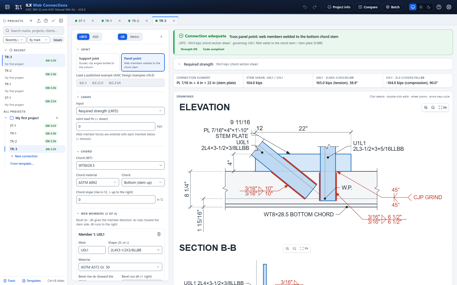
When the welds of a web member do not fit on the chord stem, add a stem plate CJP-welded to the stem tip. II.C-2 joint L1 uses PL 7/16 × 4 × 1'-10. Enter its thickness, its depth beyond the stem tip, the start of the plate along the chord (from the W.P.) and its length.
- Welds may run onto the stem plate. The weld base-metal and block-shear checks then use the thinner of the stem and the plate.
- A recommendation flags a plate thinner than the stem.
- Without the plate, the 10 in. welds of U0L1 at L1 do not fit on the stem, and the joint is NOT FEASIBLE. That is why the example adds the plate.
Chord stem shear at a panel point #
ILX finds the critical sections between adjacent members, ordered along the chord by their weld centroids. At each section it sums the force components perpendicular to the chord on each side of the cut, including the joint load at the W.P. The larger side governs.
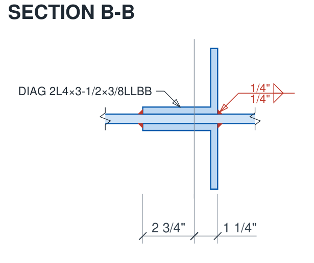
The required shear is checked against shear yielding of the stem, 0.60 Fy d tw, with d the full depth of the WT (J4.2(a)). In II.C-2 this gives 104 kips at L1 (Section A-A) and 104 − 30 = 74.0 kips at U1 (Section B-B), as published.
Panel point with a gusset plate #
Instead of welding the web members to the chord stem, you can connect them to a gusset plate on the stem.
- Choose Panel point, then under Chord set Members connect to to A gusset plate on the stem.
- Enter up to three web members (for example diagonal, vertical, diagonal).
- For each member choose Welded (heel and toe fillets, as above) or Bolted.
- Set the gusset in the Gusset plate section.
The four buttons under Load a panel-point gusset configuration load worked setups: three welded members, three bolted members, one bolted and one welded member on a sloped chord, and a single member on a bottom chord with a lapped gusset. They are not published examples.
Gusset size #
- Automatic (default). ILX sizes a rectangle along the chord that holds every member's connection (plus the edge distance beyond it) and the ends of each Whitmore section. It rounds the size up to ½ in. The editor shows the computed start, length and depth; Use computed copies them into the fields and turns automatic sizing off.
- Given. Turn automatic sizing off and enter the start (from the W.P., along the chord), the length along the stem and the depth beyond the stem tip.
- Chamfers. The corners are cut square to each diagonal at Connection end to the gusset edge beyond its welds or last bolt. A chamfer is skipped if it would cut into another member's connection.
- Gusset to stem. CJP groove weld (a butt joint on the stem tip) or Lapped on the stem with fillet welds along both edges (enter the fillet size and the lap).
Bolted members #
Enter the bolts per line, one or two bolt lines, the spacing, and the distance from the angle end to the first bolt. The gage is the workable gage of Manual Table 1-7A unless you turn that off and enter it. Bolt grade, diameter, threads, holes and joint type are set once in the Bolts section. Double angles put the bolts in double shear.
What is checked #
For each member:
- End connection. Welds as for a stem connection. Bolts: shear, plus bearing and tearout on the angles and on the gusset, summed bolt by bolt (J3.7 Commentary). Tearout uses the angle end in tension and the gusset edge beyond the last bolt. Slip resistance is checked for slip-critical joints.
- Tension. Yielding, Fy Ag. Rupture, Fu U An: Table D3.1 Case 4 for welds, and the larger of Case 2 (1 − x̄/l) and Case 8 (0.80 with four or more bolts per line, 0.60 with three) for bolts.
- Block shear of the angle legs (bolted) and of the gusset around the welds or bolts (J4.3).
- Whitmore section. lw = w + 2 l tan 30°, counted only where it lies on the gusset or the stem. Tension: yielding, Fy Aw. Compression: buckling by DG29 Table C-1. A panel-point gusset is the chevron row: K = 0.65 with the centre-line length l1 from the start of the connection back to the chord. With Given K, the K you enter is used with Thornton's average length.
- Detailing. Bolt spacing and edge distances, bolt lines inside the angle leg, and a recommended clear distance between members.
For the gusset and the chord:
- Interface forces. All member forces act along their work lines through the W.P. ILX resolves them at the gusset-to-stem interface into a normal force N, a shear V and a moment M about the interface centre. The joint load is added when it is applied to the gusset; otherwise it acts on the chord.
- Interface stresses. On the weaker of the gusset and the stem: the normal stress Ne/(tL), with the equivalent normal force Ne = |N| + 4|M|/L (DG29 App. B), and the shear stress |V|/(tL). The combination is checked with DG29's plastic interaction (p. 56): M/Mc + (N/Nc)² + (V/Vc)⁴ ≤ 1, with Mc = φ Fy tL²/4, Nc = φ Fy tL and Vc = φ 0.60 Fy tL.
- Interface weld. A CJP develops the base metal. Lap fillets are designed for the larger of the peak stress and 1.25 × the average stress (Manual Part 13), with the directional strength increase.
- Free-edge buckling (strength; DG29 App. C.4, the admissible force maintenance method). An edge region of the gusset is an embedded plate a × b with one free edge: λ = (b/t)√Fy / (5√(475 + 1120/(a/b)²)), Fcr = Q Fy (Q = 1 for λ ≤ 0.7, 1.34 − 0.486λ up to 1.41, 1.30/λ² beyond). The compressive stress fa = Nc/(bt) must not exceed φFcr (φ 0.90). Two regions are checked:
- the chord interface (b = L, a = the gusset depth) under Nc = −N + 4|M|/L when the members push the gusset into the chord;
- between adjacent members, a section square to the chord (b = its depth, a = the bottom free edge) under the force and moment of the members and the chord reaction on one side (DG29 Ex. 5.9, section b-b). This one can govern when diagonals on both sides push toward each other. The old Lg/t ≤ 2.06 √(E/Fy) rule is no longer used: DG29 explains it as a bridge fatigue rule.
- Chord stem shear. The interface force is spread along the stem (uniform from N, linear from M). The stem shear at each section is the force on one side, plus the joint load on the chord. The worst section is checked against 0.60 Fy d tw.
- Stem local yielding (J10.2 approach). The equivalent normal force Ne = |N| + 4|M|/L (DG29 App. B) is compared with Fy tw L.
Drawing #
The elevation shows:
- the gusset outline, with its ends dimensioned from the W.P. and its depth;
- the members with their welds and weld symbols, or their bolts (drawn realistically) and bolt callouts;
- the work lines meeting at the W.P.;
- the CJP or lap-fillet symbol, with the lap shown hidden;
- the Whitmore spreads and sections as hidden lines, when Show the Whitmore sections is on.
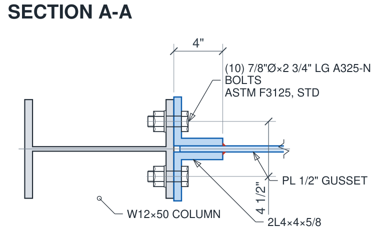
Section A-A cuts square to the chord. It shows the WT with the gusset on the stem tip (CJP) or lapped on the stem (fillets), flipped for a bottom chord. Section B-B shows the first member on the gusset, with its welds or bolts.
Limits #
- No published example covers this joint. It is verified by hand calculations and equilibrium checks.
- A lapped gusset is offset from the chord plane. That out-of-plane eccentricity is not checked; a note says so.
- The members' own buckling belongs to the truss design and is not checked.
Geometry not feasible #
ILX marks the joint NOT FEASIBLE instead of NG whenever it cannot be built:
- a weld runs off the gusset, the stem or the stem plate;
- a member runs into the chord flange;
- two web members collide on the stem;
- the diagonal collides with the clip angles;
- the clip angles do not fit between the chord flange and the gusset bottom;
- a bolt hole breaks out of an angle or lies off the column flange;
- the clip-weld returns are longer than the angle leg over the gusset;
- the gusset chamfer leaves no usable plate.
Each item names the input to change and is highlighted on the drawing.
Truss drawings #
Elevation. The view shows:
- the chord with its real flange and stem;
- the web members as their connected legs, cut with break lines, with their work lines meeting at the W.P.;
- the heel and toe welds, with AWS A2.4 symbols that carry the weld lengths (separate HEEL and TOE symbols when the lengths differ);
- bevel triangles;
- at a support joint, also the column flanges and centerline, the gusset outline and its dimensions, the clip angles, the bolts (drawn realistically, through the angle leg and the column flange), the C-shaped weld, the CJP symbol, and the vertical bolt dimensions from the W.P.;
- at a panel point, also the stem plate, its CJP and its dimensions.
Section A-A (support joint): the column I-section, both clip angles, the gusset, the bolts and the fillets at the angle toes.
Section B-B: a typical web member. The gusset or stem lies between the two angles, with the heel and toe fillets and the work-line gage.
Click any part to select it and edit its inputs. The drawing sheet carries the elevation and one section on 8½ × 11 and 11 × 17 sheets; the report also shows Section B-B.
Manual Part 13 truss items #
These follow AISC Manual 16th Ed. Part 13, "Truss Connections" (pp. 13-22 to 13-28). Where the Manual leaves a value to the engineer it is an input with a stated default, and the report shows it.
| Item | Input (default) | What ILX does |
|---|---|---|
| Minimum connection strength (p. 13-24; Spec. Commentary J1.1) | Minimum connection strength on; value 0 = 10 kips (LRFD) / 6 kips (ASD) | A web member with no force defined (P = 0) is connected for the minimum as tension. Its welds, base metal and member end are checked for it; the chord stem shear and the equilibrium advisory keep the analysis force (0). Enter a smaller value for small elements. |
| Working-line offset at a panel point (p. 13-24) | W.P. offset from the chord work line (0), + toward the stem | The web members' work lines meet at the offset point (the drawing shows the W.P. there). The chord takes M = ΔN e, ΔN being the change in chord force at the joint; it is reported for the chord design. The web members' own connections neglect the eccentricity (Spec. J1.7). |
| Support eccentricity in the column (pp. 13-25, 13-26, Figs. 13-14 / 13-15) | Column share of R e (1.0, the full eccentricity) | W.P. on the column face: the column takes R d/2 and the connection has no eccentricity. W.P. at the column centreline: R d/2 is shared by stiffness; the Manual's good practice, the default, gives the column all of it. The gusset-to-column connection is always designed for the full e = d/2. The column moment is reported for the column design. |
| Tension chord elongation (p. 13-27, Eq. 13-44) | Check the tension chord elongation (off); average service force, chord length, chord section (blank = this chord), erection clearance (0) | Δ = P l / (A E). Half of the total arrives at each support. A recommendation compares it with the erection clearance provided (shims for a shop-attached connection, slotted holes, reaming or a welded field connection). |
Verification of the truss examples #
The three published joints are reproduced end to end, LRFD and ASD, as golden tests. That is every limit state the examples print, 124 comparisons in all, each within ±1 % or 0.5 kip. They appear under Settings → Verification (connection type "Truss connection"). There are no documented deviations. Notes:
- II.C-1 weld coefficient. AISC interpolates Manual Table 8-8 (C = 1.50); ILX solves the IC method on the same weld group (C = 1.496).
- Rounding. Small differences in the clip-angle shear areas and in the column-flange prying come from the example rounding intermediate values (18.8 in.², tc = 1.14 in.).
- Member end distances. The examples give these only in their figures. ILX's examples use end distances that make the welds fit the stems as drawn. U1L2 at joint U1 fits only in a narrow window (3⅜ to 3 7/16 in.), which is why the example uses unequal welds instead of a stem plate.
Truss limitations #
- Support-joint gusset weld. It is CJP, as the example; a fillet-welded interface is designed only for a panel-point gusset.
- Bolted members. Bolted web members are available on a panel-point gusset only; at a support joint and on the stem they are welded.
- Chords. Chords of W or HSS shapes are planned.
- Members at a support joint. A support joint takes one diagonal. Further members in the list are ignored, with a note.
- Auto-design and Compare. They are not available for truss connections yet.